@Ghar,
Not sure I know what you're saying.
We have t>0 so the switch is closed.
Why can I short circuit the sources ?
Are you saying Req= R // R // (R1+R2) // (R1+R2)
And then T = Req X C. If so, I already tried it and it didn't work.
You can short the sources because the time constant only depends on the R and C. Voltage sources are 0 resistance.
Like I said I confused myself so let me sort that out and I can say more...
Edit:
So I went to simulate it to confirm and the initial voltage messed me up for a moment.
Ok so like I said, at the right you have R1 || R2.
On the left you have an ideal voltage source, so that shorts out the two R's. What's remaining?
The capacitor loop has the stuff on the right in series with the stuff on the left so you add your results.
Edit 2:
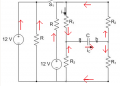
Attach a drawing with the current directions... it helps you see what resistances you use and how.
So you'r saying Req= R1 + R2 + R1 + R2 ( the resistances on the right added with the resistances on the left). I didn't get why it's like that but I tried it and it didn't give me a correct answer.
Short the voltage sources and calculate the resistance between points a and b. The same procedure for calculating the Thevenin resistance of a circuit.
So you'r saying Req= R1 + R2 + R1 + R2 ( the resistances on the right added with the resistances on the left). I didn't get why it's like that but I tried it and it didn't give me a correct answer.
Sorry mik3 for not replying to you (slipped my mind after tried to figure our what Ghar said)
Req=R1//R2(left side)+R1//R2(right side) worked. Thank you both
But could you explain to me the thought process ?
You short-circuited the voltage sources because they don't affect the outcome. But I don't see how you got Req=R1//R2(left side)+R1//R2(right side).
Sorry mik3 for not replying to you (slipped my mind after tried to figure our what Ghar said)
Req=R1//R2(left side)+R1//R2(right side) worked. Thank you both
But could you explain to me the thought process ?
You short-circuited the voltage sources because they don't affect the outcome. But I don't see how you got Req=R1//R2(left side)+R1//R2(right side).
From elementary speculation the bridge capacitor is eleminated from the circuit imaginarily,thus the last two branches are in parallel. It seems that all branches are in parallel when following through with what Mik3 said about short circuit the voltage sources.
Sorry mik3 for not replying to you (slipped my mind after tried to figure our what Ghar said)
Req=R1//R2(left side)+R1//R2(right side) worked. Thank you both
But could you explain to me the thought process ?
You short-circuited the voltage sources because they don't affect the outcome. But I don't see how you got Req=R1//R2(left side)+R1//R2(right side).
You have to find the resistance seen by the capacitor, which in this case, is the Thevenin resistance of the circuit. Just apply Thevenin's theorem between points a and b. You can verify that by simulations or experimentally.
@Ghar
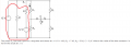
You're saying that everything in the red loop in parallel to R2. For me I see that everything in the red loop is in parallel to the branch that has both R1 and R2.
About you referring to the current directions you posted. I'm afraid I don't know how the directions can help me understand what you're trying to explain to me.
i.e. When I look at the picture I don't see a new piece of information.
Hold on, I'm trying to redraw it to show it better and I think I made a mistake in my equation with RV. The case with RV = 0 is correct though.
Edit:
I'll have to actually derive the equation with RV, I messed up doing it by inspection. What I said only applies with the ideal voltage source.
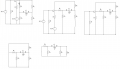
This diagram should show why that's correct at least...
oh now I see, I would have never thought of that!
Thank you a lot
Any chance you could take a look at this thread it's the exact circuit but now am trying to find V and I. I detailed what I tried to do but no success yet. There has to be something I'm missing.

 Facebook
 Google
 GitHub
 Linkedin