Hello Guys,
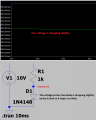
so i was simulating the circuit below and i am wondering why is the voltage drop on the diode not the same as on the resistor, as i made the ohmic resistor of the diode equals to the resistance of the resistor?
Can you please explain to me how i can determine the voltage drop on a diode?

so i was simulating the circuit below and i am wondering why is the voltage drop on the diode not the same as on the resistor, as i made the ohmic resistor of the diode equals to the resistance of the resistor?
Can you please explain to me how i can determine the voltage drop on a diode?