so you're saying if you need a transistor to switch lets say 1amp; then using the 1/20 ratio the base to emitter current should be no less than 1/20th of an amp or 0.2amps.
The datasheet for European little transistors (BC548, BC337) says for a poor (0.6V or 0.7V) saturation the base current should be 1/20th the collector current. But they saturate better with 1/10th.
The datasheet for American little transistors (2N3904, 2N4401) says for a good (0.3V or 0.4V) saturation the base current should be 1/10th the collector current.
Many power transistors say for a 10A collector current the base current must be 3.3A for a horrible 3V saturation voltage. The 2SA1302 Japanese power transistor in this thread says for a 10A collector current the base current must be 1A for horrible 3V saturation voltage.
The transistor is a voltage controlled current device meaning you need to look at the external circuitry to determine the voltage across the collector and emitter (a current source can have any voltage across it...).
To get a transistor to operate as a switch both the Base Emitter and Base Collector junction need to be forward bias because the collector isn't as heavily doped as the emitter the required forward bias for the base collector junction is usually ~0.2V less than the base to emitter junction.
A model for a transistor as a switch would be a 0.7V voltage source between the base and emitter & a 0.2V voltage source between the collector and emitter with a base current greater than (collector current)/(hfe_minimum), 1/10th the collector current is a good number.
An NPN transistor is a bad choice for this application.
It must be configured as a low-side-switch, which means that all the IO lines that drive it must be set HIGH before you shut it down.
Additionally, the VCE sat. voltage lifts the ground of the module, which impacts the logic signal noise immunity.
A P-FET is the way to go here, or a PNP transistor as 2nd choice.
1) Its not much wise to look for American transistor data into russian web service. There one may look instead for russian transistors data. Simply the datasheet the may happen to be old, with mistakes etc. But there is no much needed any of those data for Your task anyway.
2) So, the exact current in base circuit You need is I(c) /beta. However in order to minimize the power loss and temperature instabilities always there are introduced a specific over-saturation factor being between 1,5 and 3. If it is going above, the switching-off becomes excessively slow. Thus the factor of 10 is harmful.
3) So, sad to tell but beta must be known with some 1.5...2-fold accuracy at least instead those written in datasheet "will be between 2 and 20 000" (Im kiding). So, as You have measured the beta, apply the resistor from base to earth creating i(1)=0,7V/R(b-gnd) and i(2)=i(c)/beta. There R(b-gnd) may make a thermal stability setup, mostly 1k0 is good, some cases even 2k is permittable but never beyound the 10k, and some cases even so small as 100 ior 200 Ohms gives a better stability. Then i(1)+i(2) must be equal to i(3) coming into play from Vcc, thus the R(Vcc-B)=(Vcc-0.7 Volts)*i(3).
Example - beta=80, i(c)=80, saturation factor=2. Then i(2)=80/80*2=2 mA. i(1)=0.7/1k=0.7mA, i(3)=2+0,7=2,7 mA. If I guess Your Vcc=5V then R(Vcc-B)=(5-0,7)/2,7m=1,59k or nearest nominal 1k5.
4) If there the more exact thermal analysis is demanded, just use the specific soft for it, one good between many is AppCad in submenu - "biasing".
Thank you guys for these detailed answers, it really helps to clarify the workings of a transistor;
The pdf attachment by Muawiya is also very useful diagram of a schematic look at how a transistor operates as a current sink.
It also clarifies why transistors Vbe is usually quoted as 0.7 - 0.6 Volts; that's because Vbe junction is a basically a diode. And I think Vcb is a Diode with resistor; might be mistaken here though.
Once I understand these things, it becomes a bit easier to reason about BJT transistors.
I'm having some trouble working out the correct value for a base resistor to use with an NPN transistor. I've tried researching it but I've come across so many different calculators and formulas that I'm completely confused!
What I need to do is use the transistor as a switch. I'm using a PICAXE IC's output to turn the transistor on/off. The transistor is then to be used to turn on/off a bluetooth module that requires 40ma. (a picaxe can only output 20ma max from one of it's pins apparently)
I enjoyed the back-and-forth in this old thread. I do a bit of electronics, but consistently fail to learn the basics.
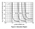
Anyway, I found this imo illuminating diagram! I deem Ic/100 unwise, while Ic/10 is possibly overkill. I'll personally use Ic/50 in the design I'm currently at. I am not saying it's right, but I feel confident that it's not wrong.
I enjoyed the back-and-forth in this old thread. I do a bit of electronics, but consistently fail to learn the basics.
Anyway, I found this imo illuminating diagram! I deem Ic/100 unwise, while Ic/10 is possibly overkill. I'll personally use Ic/50 in the design I'm currently at. I am not saying it's right, but I feel confident that it's not wrong.
This thread is 3 years old, but probably still relevant.
If you have a problem with some basics you can always ask here in this forum. Lots of people are willing to help.
Any question is a good question, and most of us here realize that learning the basics at first can seem difficult, but it gets easier as time goes on if you have a place to ask questions.
With this post are you talking about learning about the saturation of a bipolar transistor?
Most people use Ic/10 but if you think that is an overkill then i just say it really depends highly on the transistor. The purity of the die makes a difference here and some transistors are made better than others. With a really good transistor you may be able to use Ic/50 but that is getting a bit low i think. Maybe Ic/30, unless you have a really good transistor.
All datasheets for little transistors guarantee a good saturation with the base current at Ic/10.
European BCxxx transistor show a not very good saturation at Ic/20.
Zetex (or as it was called at one time) made some really good transistors with very pure dies. Some of their transistors had very high gain and so the gain near Vsat was higher than usual too if i remember right. We can look at some different part numbers to see how that works.
There's no way to stop the collector base diode from stealing current from the internal base, but if the current gain is very high it may still allow a lower than usual base current to keep it in sat, but what else could happen is the transistor will not be completely in sat, but when compared to other transistors it may look like it is because the collector emitter voltage is so low anyway, even before complete sat is reached.
If i get a chance i'll show some examples.
I enjoyed the back-and-forth in this old thread. I do a bit of electronics, but consistently fail to learn the basics.
Anyway, I found this imo illuminating diagram! I deem Ic/100 unwise, while Ic/10 is possibly overkill. I'll personally use Ic/50 in the design I'm currently at. I am not saying it's right, but I feel confident that it's not wrong.
Keep in mind that those curves are for the mythical "typical" transistor operating at a junction temperature of 25°C.
You can certainly decide to use Ic/50 if you want, but you know that beta values easily vary from transistor to transistor by an order of magnitude, yet you are uncomfortable using Ic/100 yet are willing to use Ic/50, when that is a mere factor of two difference? You are the designer and you get to accept whatever consequences come about from your decisions. If you are satisfied that the actual transistor that you happen to use, operating at the temperature that it actually happens to be operating at, will perform in an acceptable way, then you may certainly do so.
To be sure, there really is nothing magical about Ic/10. It is nothing more than tradition, when all is said and done. Many decades ago, when discrete NPN transistors were first being commercialized, some manufacturer (if we were to go back and find enough early databooks, we could probably figure out which one) chose to, for some reason, characterize the saturation performance values of their transistors at a forced-beta of 10. It's hard to say if anyone could go dig up the reason, as it was likely decided over lunch, but it probably was nothing more significant than that being a nice round number that served to place all of their transistors (or at least the ones they were discussing) firmly into saturation. So they characterized their transistors at that operating point and published their data sheets. By using the same operating point for their saturation parameters, engineers could more easily compare the performance of different transistors. Other manufactures were aware of this, of course, and so they used the same operating point for their characterizations so that they could draw comparisons between their transistors and the other company. Others simply followed suite and it became the defacto saturation characterization point for small signal transistors that survives to this day.

 Facebook
 Google
 GitHub
 Linkedin