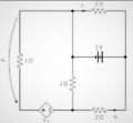
Calculate the voltage V4 and current i6 of the circuit in the figure using only Kirchhoff and law of nodes and meshes

Thread Starter

abdaelawad

Joined Dec 17, 2022
7
I tried to solve the equations I got but when I make substitutions I get to a deadlock where I can't substitute anything anymore.

The equations I obtained are:

i2=i1+i2
i3=i4+i5
i5=i7-i6
i2=i4+i6

3i2-i1R1-i5R2=0
2v-i2R3=0
-i6R4+2v-i5R2=0
Could someone help me understand step by step what procedures to perform to get to the solution.

I thank you all anyway and have a good evening, see you soon!

IMG_20221217_215748.jpg
 

WBahn

Joined Mar 31, 2012
30,056
First thing to do is look at your equations and ask if they make sense.

Your very first equation is

i2 = i1 + i2

If this equation is correct, then what MUST the value of i1 be?

Does that make sense (for whatever current i1 happens to refer to?)

Speaking of which, if someone gave you that diagram and those equations, would YOU know what i1, i3, i4, or i5 were?

Can you tell which resistors are being referred to by R1, R2, R3, and R4?

Well, neither can we.

We MIGHT be able to infer what some of these are by pulling apart your equations and guessing what you meant with each of them, but why should we? It's YOUR responsibility to communicate your work clearly to others.

So annotate your drawing to include all of the reference designators you use in your equations.

Then, show YOUR best effort to work the problem as far as you can.
 

Thread Starter

abdaelawad

Joined Dec 17, 2022
7
Good morning, sorry I misspelled the first equation, it would be:

i3=i1+i2

However, I think this is the difficult thing because all I have for this exercise is shown in the figure itself.

Let me explain, the starting exercise is just this here (I attach file), I drew it on paper so that you can understand it better.

So I wanted to understand based on an exercise that is given without further reference to the elements of a circuit how you can reason about it.


Screenshot (129).png ( this generator is worth 3i2, it doesn't read well)
 

WBahn

Joined Mar 31, 2012
30,056
Again, I have no idea what i3 or i1 is. I am NOT a mind reader!

If you use a current or a resistance or a voltage that is not indicated on your schematic, you need to indicate it on the schematic!

Also, you are using a convention for indicating voltage that is ambiguous. The best way it to put a '+' and a '-' on the nodes that the voltage is across. But I realize that some parts of the world use an arrow as you have. Unfortunately, I've seen it both where the head of the arrow points to the positive side of the defined voltage (the arrow indicating a voltage gain) and where it points to the negative side (the arrow indicates a voltage drop). Which custom are you using?
 

Thread Starter

abdaelawad

Joined Dec 17, 2022
7
This is how I put the verses of the currents, but my question is, if for example you were faced with such a circuit (I am referring to the printed picture), how would you write the equations?


IMG_20221218_194445.jpg
You have as currents marked only i2 and i6.

And you have to find v4 and i6.

Unfortunately, I can't solve with the equations I got.
 

WBahn

Joined Mar 31, 2012
30,056
Your handwriting is very difficult to read (you should work on that -- take your time to print very neatly in your work, it will pay off).

I'm not sure exactly what constraints have been placed on you when you say that you can only use "Kirchhoff and law of nodes and meshes". There are two formalized analysis techniques usually known as Node Voltage Analysis (or Nodal Analysis) and Mesh Current Analysis. These are just systematic ways of applying Kirchhoff's voltage and current laws to a circuit. Are those fair game for you to use, or have you not gotten to them yet?

It looks like you are going down the road of a brute force application of KCL and KVL directly, so I will assume that this is the constraint you are working under.

You've identified and labeled four nodes, so use that information to annotate your work. It will make it a lot easier to communicate your work to others (be it us, or the grader).

For KCL equations, you can either set them up as the total sum of currents is zero, or set them up as the sum of currents going into the node are equal to the sum of the currents going out.

I would recommend the latter since it eliminates all the minus signs from your set up equations.

I would recommend NOT doing a mix of the two, where you have currents on both sides of the equation and some are positive and some are negative -- that's just asking for a silly sign error.

Also, be consistent. If you choose to call a current going into a node positive or if you put the sum of the currents going into the node on the left, then stick to that convention throughout. Technically, it doesn't matter since each equation is a standalone entity, but if you are consistent in your work, you are less likely to make mistakes and more likely to catch the ones you do.

I usually write the sum of the currents going into the node on the left and the sum of the currents leaving the node on the right.

Similarly, with your KVL equations, decide if you are going to sum of the voltage gains or the voltage drops around the loop and then be consistent. I tend to write the sum of the voltage drops across resistors on the left and set that equal to the sum of voltage gains across the sources on the right.

I would also recommend being consistent in the direction of your loops. Again, strictly speaking it doesn't matter, but consistency is key to avoid and catching mistakes. I generally always go around the loops clockwise.

KCL
(A) i1 + i2 = i3
(B) i3 = i4 + i5
(C) i5 = i6 + i7
(D) i4 + i6 = i2

Do you notice anything about i1 and i7 that could be useful?

KVL
(M1) i1·R1 + i5·R2 = (3 Ω)·i2
(M2) -i2·R3 = -2 V
(M3) -i5·R2 - i6·R4 = 2 V

Note that you have the 2 V source shown in one polarity in two of your figures and the opposite polarity in the third. Which is it? You need to really be careful about this, because you will end up working a different problem that is guaranteed to produce the wrong answer and do so in such a way that it is almost impossible to catch because you correctly solved a different problem. For your 2 V source, I used the polarity you showed in the first to figures.

The next step is to stop and verify that your setup equations are correct. This is where all of the EE takes place. Once you move past this point, it is all algebra. Any mistakes you've made in your setup equations cannot be caught after this point, so verify each and every single one of them consciously and deliberately before moving on.

Notice that my equations do not quite match yours. So look at the ones that don't and determine which ones are correct and which ones are wrong (and I can't rule out the possibility that I made a mistake).
 

Thread Starter

abdaelawad

Joined Dec 17, 2022
7
First of all thank you for your answers, I tried to use the equations you gave however I am not getting the results back.

The results given are:

v4= 2 V

i6= -3/2 A

If the results don't come back to you, don't worry thank you anyway.
 

WBahn

Joined Mar 31, 2012
30,056
First of all thank you for your answers, I tried to use the equations you gave however I am not getting the results back.

The results given are:

v4= 2 V

i6= -3/2 A

If the results don't come back to you, don't worry thank you anyway.
There is no way I can tell you where you are going wrong unless you show your work, step by step.
 

WBahn

Joined Mar 31, 2012
30,056
What are you getting for i2?

You should be able to look at that circuit and immediately state what i2 is by inspection. If your subsequent work doesn't agree with that, then you know something is wrong.
 

Thread Starter

abdaelawad

Joined Dec 17, 2022
7
The work I did I wrote in my first question and in the photos, I drew currents and applied nodes and meshes getting the equations described above, then I started substituting values from the second mesh getting i2=1A.

From which on I noticed that I can't substitute anything anymore because I would have equations with multiple unknowns together.

You if faced with this exercise following the original (printed) text, how would you write the equations? (Leaving out what I did which is probably wrong)Attach files
 
abdaelawad, can you see that R3 is connected directly across the 2 volt source? So then what is the current in R3? Mesh 2 doesn't need to be solved; it's a given. You only need to solve mesh 1 and mesh 3. Can you write the mesh equations for those two meshes?
 

WBahn

Joined Mar 31, 2012
30,056
The work I did I wrote in my first question and in the photos, I drew currents and applied nodes and meshes getting the equations described above, then I started substituting values from the second mesh getting i2=1A.

From which on I noticed that I can't substitute anything anymore because I would have equations with multiple unknowns together.

You if faced with this exercise following the original (printed) text, how would you write the equations? (Leaving out what I did which is probably wrong)Attach files
What you did was almost certainly wrong, but how can I possibly help you figure out what you did wrong if you refuse to show what you did to get the answers you got?

I am NOT going to just work the problem for you and show you all the steps so that you can turn it in and claim credit for work you didn't do. Even if that's not what you are trying to do, just showing you the steps isn't going to help you -- it will just make you think that you've learned something when you haven't. You need to struggle and fight with it, even if you are going about the wrong way. By showing your work, we can spot where you went off the rails and point that out to you so that you can learn from your mistakes. Otherwise you will just continue making the same mistakes over and over.
 

Thread Starter

abdaelawad

Joined Dec 17, 2022
7
What I did yesterday was to try again with the new equations given above, and what I got was again a deadlock where I can no longer substitute anything into the mesh equations.

(I attach photos)

IMG_20221219_082132.jpg
 

WBahn

Joined Mar 31, 2012
30,056
You REALLY need to work on making your work neat, organized, and presentable. This is for YOUR benefit. Put yourself in the grader's position. They have dozens of papers to grade and likely very little time to devote to each one, not to mention the sheer drudgery that grading is by its very nature. If they see a paper where is hard to tell what many of the characters even are, let alone where they came from, how much time are they going to spend on trying to figure out how much of the work is correct before just assigning a very low grade and moving on to the next paper. Now consider that a large fraction of what gets turned in falls into this category of being poorly organized and difficult to follow and imagine what happens when they see a paper that is very neat, very organized, and very easy to see what the line of reasoning is. It's like a breath of fresh air! They WANT to savor it and will find ways to award as much partial credit as possible, and the fact that it is so well presented makes it easy to find those ways.

I actually got a paper back in which the grader wrote that although I had made a minor mistake early on that resulted in nearly all of my answers being wrong (and in this course the policy was that the final answer was the primary basis for the grade), that they just couldn't bring themselves to take of any points from work that was so beautiful. I was puzzled by that, since I assumed my work was not that much different from others since I was merely following the style standards set forth in a prior course in the same department. But then I became a grader a year or so later and I very quickly realized exactly why they would make that remark and I completely sympathized with it. I also quickly realized the natural bias that I had for well-presented work and against sloppy, hard-to-follow work. At first I tried to fight it, but soon I realized that it was not only natural, it was appropriate because it was a direct evaluation of the student's ability to communicate effectively, which is a large part of an engineer's job.

So in addition to neatness and consistency (for instance, some of your i's look like upside down v's while others look like the normal straight line), don't make the reader play detective and have to go sift through everything trying to figure out where a particular line comes from. Make it clear what you are doing and why. If nothing else, this let's the grader understand what your intent was so that even if you make a mistake, they can determine whether it was a mistake based on not understanding a concept, or just a silly math error.

Finally, you need to track your units throughout your work. You made a mistake in one of your equations that, had you tracked your units, would have stood out as being wrong. But because you didn't, it went uncaught even though it would guarantee that all of your work after that point would be useless. I realize that the proper tracking of units is simply not taught, but that that doesn't mean that YOU can't apply it. If you do, you will avoid making a lot of mistakes and catch a good fraction of the ones you are going to make anyway. You will likely see your grades go up significantly as a result.

Consider this line of your work, which just appears out of nowhere:

1671469108461.png

I had to sift through all of the equations trying to figure out where this came from. In the end, I was able to determine that it came from taking:

i3 = i1 + i2

and using it to eliminate i1 from

1671469281634.png

But you made a mistake in doing so. So let's see what would have happened had you tracked the units properly.

First off, the problem says that the output of the current-controlled voltage source is three times the current through R3. But that makes no sense, because if you multiply a current by three you get a current that is three times as large -- you do NOT get a voltage, which is what that source is outputting. The author was sloppy because they don't know how to properly work with units (and this is, sadly, all too common).

That "3" is actually "3 volts output for each 1 ampere of current in R2", or "3 V/A". Although this is not a resistance, the units are the same, so this could also be written as "3 Ω", This is why a current-controlled voltage source is also known as a transimpedance amplifier. You can use either "V/A" or "Ω", but you can't just ignore it (not if you want to track the units properly).

So your loop equation should have been

\(
\left( A \right): \; i_3 \; = \; i_1 \; + \; i_2 \\
\ldots \\
\left( M_1 \right): \; i_1 R_1 \; + \; i_5 R_2 \; = \; \left( 3 \Omega \right) i_2
\)

Now it is trivial to see that each term in this equation has units of voltage (a current multiplied by a resistance), and is therefore dimensionally consistent. Also, since the whole point of a mesh equation is to sum of voltages, each term NEEDS to have units of voltage.

Notice that each equation is labeled to indicate which node or which mesh in the diagram it comes from. This also gives a very handy way to refer to these equations later.

\(
\text{Using (A) to eliminate } i_1 \text{ from (M1):} \\
\left( EQ\;1 \right): \; \left( i_3 \; - \; i_2 \right) R_1 \; + \; i_5 R_2 \; = \; \left( 3 \Omega \right) i_2
\)

Equations that you will refer to later should have some kind of label. Since you probably won't know which equations you will and won't use, just always leave enough space to add an identifier later if you need it.

If I had made the same mistake you did, my result would have been

\(
\text{Using (A) to eliminate } i_1 \text{ from (M1):} \\
\left( EQ\;1 \right): \; \left( i_3 \; - \; i_2 \right) R_1 \; + \; i_5 R_2 \; = \; \left( 3 \Omega \right)
\)

Now the left hand side has units of voltage while the right hand side has units of resistance. They can't be equal, so I would have immediately known I screwed something up and I would have stopped right there to figure out what went wrong and correct it before proceeding (down a path guaranteed to be nothing but a pure waste of my time).

Now, it's possible (probably) that you left out the i2 from your equation because off to the side somewhere you noted that i2 = 1 (which it doesn't, it equals 1 A). If that's the case, then that "3" should have been "3 V".

By not making it clear what you are doing, the grader has no way to know whether you did it right, but were just sloppy with units, or whether you messed up and accidentally dropped the i2 altogether. Since you still have an i2 on the left side of the result, I would not give you the benefit of the doubt if I were grading this.

With a surprising little bit of practice, tracking and checking your units at every step will become second-nature.

Okay, on to other things.

I mentioned before that your setup equations capture ALL of the physics (the EE involved) in the problem and that everything after that is math. So let me expand on that a bit. Make a clear delineation between these two portions of your work. Write down the setup equations and draw a line under them separating them from the math. Don't do any math in the setup equations -- make them match the diagram as directly as possible in order to make them easy to verify. Also, make the effort to ensure that you have ALL of the setup equations in place before moving on to the math section where you manipulate them to get your answer. The first thing to consider is whether you have enough equations.

How many unknowns do you have? Your have second unknown currents and one unknown voltage (the main thing you are solving for). That's eight unknowns.

How many equations do you have? You have second, although you really only have six. So you need two more.

The equation for v4 is straightforward, but it should be included in the setup equations because it captures some of the physics, not the math.

But why do I say you only have six?

Because you have four essential nodes (the ones you labeled A through D), but only three of them are independent. If you give me the equations for all but one essential node in a circuit, I can use them to come up with the last one -- that's what KCL is all about.

So you are missing an equation.

Remember I asked you whether or not you could see a relationship between i1 and i7? By ignoring that question, you've left yourself with too many unknowns.

Now for the math.

There are many ways to solve systems of linear equations, but let's stick to the basics. Pick one variable and eliminate it from all of the other equations. This reduces the number of equations you have left by one, as well as eliminating a variable from them. Then pick another variable and do the same thing. It doesn't matter which one you eliminate (except don't eliminate the one you are ultimately trying to solve for unless you are willing to solve for some other variable and use that result to come back at the one you really want, which is sometimes the easiest route to take.
 
Top