
Hey all,
I'm trying to build a photography light based on a video on Youtube: VID, and I've been running into an issue with my DC-DC boost converters burning out for a reason I can't identify.
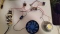
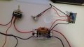
The circuit is pretty simple: A 120W AC-DC power adapter is outputting 12V to the boost converter (LINK), which is bumping it up to 32V, with a constant-current limit of 3A. The boost converter is then outputting to a 100W LED chip rated for a forward voltage of 30-34V and a max current of 3.5A. The power adapter is also feeding into a dc-dc step down module which is regulating the current to under-volt a 12V computer case fan, for cooling.
Now, despite burning out the first board for a reason I think i understand, I got the second board to work steadily and without failure. That was, until I turned it off one time.
I had been running the LED for about a half hour (and this was the fifth time ive done so), and then when I was done, i flicked the switch in the circuit to cut the power between the laptop adapter and the rest of the equipment, and this is when I noticed that the powder adapter's LED light was flickering, as it had done when the last board burned out and was shorting. Realizing what was about to happen, i went to pull the plug, but I was too slow and the second board burnt out. The third and most recent time I rebuilt the system from scratch, I actually made improvements to the design in the video, choosing to connect all the components on a through-hole PCB, instead of having them just floating in the air, to ensure secure and reliable solder connections. I also made sure to use the best, highest-quality switch and potentiometer i could find. The system worked fine, running for 15 minute intervals every time. I started final assembly, and started gluing the components into their case, and so i decided to test the system one more time before it was all glued in for good. I hooked up my multimeter in series to read the current passing through the LED, and turned it on. Everything worked perfectly, but the multimeter was giving a negative current reading. Just for the sake of my OCD, I turned everything off, disconnected the multimeter, and swapped the leads so that the value would read as positive. When i turned the light back on, without having changed anything else, it turned on for a second, and then immediately burned out the MOSFET on the boost converter. I'm at a loss...
The component that is burning out is the NCE6075K N-Channel Enhancement MOSFET (DATASHEET), and I don't know enough about electronics to figure out why exactly.
I'm so frustrated and upset with this darn project. It was supposed to be easy and simple and cheap but ive sunk tons of money into these boards, and they take weeks to get here each time. I can't keep doing this. I've even been adding heatsinks to the boost converters from the start, AND they've been actively cooled by the fan that's cooling the LED.
I've checked, double-checked, and even quintuple-checked the wiring, and its EXACTLY the same as his is in the video. His system worked fine, mine keeps blowing.
Please, any help is greatly, greatly appreciated. I just don't know whats wrong.
I've attached some pictures of the circuit below. I hope it helps.
PS. Please note that I am aware that this circuit is not wonderfuly designed.. I KNOW that the power switch should be switching the power supply, not the LED (though to be fair, I actually added another switch in front of the power supply, and thats the one i was using when testing, and when it died), and I KNOW that fans shouldnt be slowed by under-volting, but instead by PWM. The point of this post is simply that the design in the video --be it good or bad--, when built by the guy in the video, WORKS, and mine, when following the exact same steps, using virtually identical parts, DOESNT.

.jpg")


I'm trying to build a photography light based on a video on Youtube: VID, and I've been running into an issue with my DC-DC boost converters burning out for a reason I can't identify.
The circuit is pretty simple: A 120W AC-DC power adapter is outputting 12V to the boost converter (LINK), which is bumping it up to 32V, with a constant-current limit of 3A. The boost converter is then outputting to a 100W LED chip rated for a forward voltage of 30-34V and a max current of 3.5A. The power adapter is also feeding into a dc-dc step down module which is regulating the current to under-volt a 12V computer case fan, for cooling.
Now, despite burning out the first board for a reason I think i understand, I got the second board to work steadily and without failure. That was, until I turned it off one time.
I had been running the LED for about a half hour (and this was the fifth time ive done so), and then when I was done, i flicked the switch in the circuit to cut the power between the laptop adapter and the rest of the equipment, and this is when I noticed that the powder adapter's LED light was flickering, as it had done when the last board burned out and was shorting. Realizing what was about to happen, i went to pull the plug, but I was too slow and the second board burnt out. The third and most recent time I rebuilt the system from scratch, I actually made improvements to the design in the video, choosing to connect all the components on a through-hole PCB, instead of having them just floating in the air, to ensure secure and reliable solder connections. I also made sure to use the best, highest-quality switch and potentiometer i could find. The system worked fine, running for 15 minute intervals every time. I started final assembly, and started gluing the components into their case, and so i decided to test the system one more time before it was all glued in for good. I hooked up my multimeter in series to read the current passing through the LED, and turned it on. Everything worked perfectly, but the multimeter was giving a negative current reading. Just for the sake of my OCD, I turned everything off, disconnected the multimeter, and swapped the leads so that the value would read as positive. When i turned the light back on, without having changed anything else, it turned on for a second, and then immediately burned out the MOSFET on the boost converter. I'm at a loss...
The component that is burning out is the NCE6075K N-Channel Enhancement MOSFET (DATASHEET), and I don't know enough about electronics to figure out why exactly.
I'm so frustrated and upset with this darn project. It was supposed to be easy and simple and cheap but ive sunk tons of money into these boards, and they take weeks to get here each time. I can't keep doing this. I've even been adding heatsinks to the boost converters from the start, AND they've been actively cooled by the fan that's cooling the LED.
I've checked, double-checked, and even quintuple-checked the wiring, and its EXACTLY the same as his is in the video. His system worked fine, mine keeps blowing.
Please, any help is greatly, greatly appreciated. I just don't know whats wrong.
I've attached some pictures of the circuit below. I hope it helps.
PS. Please note that I am aware that this circuit is not wonderfuly designed.. I KNOW that the power switch should be switching the power supply, not the LED (though to be fair, I actually added another switch in front of the power supply, and thats the one i was using when testing, and when it died), and I KNOW that fans shouldnt be slowed by under-volting, but instead by PWM. The point of this post is simply that the design in the video --be it good or bad--, when built by the guy in the video, WORKS, and mine, when following the exact same steps, using virtually identical parts, DOESNT.
Attachments
-
 119.2 KB Views: 25
 -
 96.9 KB Views: 25
")


