Building solar led street numbers, is this n-P-n right?

Thread Starter

gershwing

Joined Dec 14, 2021
3
Hi all, i'm putting together a set of backlit numbers for my street front (the neighbors constantly get our uber-eats)

The goal is a basic outdoor LED, daytime charges the battery, LEDs come on automatically at dusk.

The numbers have a total of 14 white leds in series and using benchtop PSU i've confirmed they'll run happily at 43v 600ma, though i could throw in a 10k resistor to drop the current a little for longevity and power saving. i've also checked the battery and XL6009 can power the leds

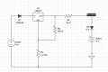
The only part I'm not familiar with is n-P-n Transistors, i've put together the below and i think it's right but thought i'd ask for confirmation.

1639909079260.png

i'm reasonably confident that when 7v flows from the LM317, this will pass through the Transistor base, out the Collector, charging the battery.
When the LM317 voltage drops (at dusk) it'll turn on the transistor load, sending power to the XL6009, which will output the required 43v
 

Ian0

Joined Aug 7, 2020
9,816
No, it won't. The base-collector diode has its anode on the collector and its cathode on the base. It will be reverse biassed if the solar voltage is greater than the battery voltage and no current will flow.
Not only that, the transistor's emitter will be at zero volts, and the base will be at 9V - it only takes 6V to damage the base-emitter junction.
Connect the emitter to the battery and the collector to the load, add a bypass diode (say a Schottky) across the base-emitter junction so that it can charge the battery, and add a resistor in series with the base, otherwise the current through R2 and R3 will flatten the battery.
 

sghioto

Joined Dec 31, 2017
5,390
i've put together the below and i think it's right but thought i'd ask for confirmation.
There's a lot wrong with this setup.
From the resistor values shown for the LM317 the output voltage is only 1.25 volts.
Even if the 2N3906 is configured correctly the max current rating is only 200ma.
From what I have read the max output from the XL6009 is 35 volts.
Seems like the whole LED string is way over powered. 600 ma at 43 volts is 25 watts. What is this outdoor LED setup exactly?
What type of battery are you using? How many hours do you expect the LEDs to be on?
Is 220ma from the the solar cell enough to charge the battery if the night time draw is actually about 4 amps if the LEDs are drawing 600ma.
 
Last edited:

Thread Starter

gershwing

Joined Dec 14, 2021
3
From the resistor values shown for the LM317 the output voltage is only 1.25 volts.
Can you let me know how you came to this, i used VOUT= 1.25V (1 + R2/R1)
ie VOUT= 1.25V (1 + 1200/240) = 7.5V

however the simulation is giving ~5.8V, which i can't account for
1639990752523.png

Even if the 2N3906 is configured correctly the max current rating is only 200ma.
good point, i just threw the simulations default nPn transistor in, but will double check values

From what I have read the max output from the XL6009 is 35 volts.
I think there are some models where the voltage is limited like this, but i selected and bench tested this one and have bench tested to confirm the advertised 50V Output voltage

Seems like the whole LED string is way over powered. 600 ma at 43 volts is 25 watts. What is this outdoor LED setup exactly?
it's 14 white LEDs (3-3.2v, 20ma forward voltage) in serial, drawing 43v. i could drop the current a little

What type of battery are you using? How many hours do you expect the LEDs to be on?
it's a Turnigy NiMH, 5C Cells in series, for a total of 6V, 4200mAh. at 60mA, it should run for 70 hours (4200/60)

Is 220ma from the the solar cell enough to charge the battery if the night time draw is actually about 4 amps if the LEDs are drawing 600ma.
you're right, 220ma is probably slightly underkill here, .1c would be 420mA, might seek a higher current charger.
 

Attachments

Ian0

Joined Aug 7, 2020
9,816
Have you allowed for the dropout voltage of the LM317? The datasheet says you should allow for 3V across the device.
9V, less 0.7V for the diode, less 3V for the regulator gives you 5.3V.
3V dropout is the maximum, so expect just a little more output, and 5.8V looks about right.
 

Thread Starter

gershwing

Joined Dec 14, 2021
3
Have you allowed for the dropout voltage of the LM317? The datasheet says you should allow for 3V across the device.
9V, less 0.7V for the diode, less 3V for the regulator gives you 5.3V.
3V dropout is the maximum, so expect just a little more output, and 5.8V looks about right.
ah thanks. stupid me, i forgot about that, will check for a LDO or otherwise go with a 12v panel
 

AnalogKid

Joined Aug 1, 2013
11,043
If the LEDs are rated for 20 mA, why do your posts say you need an output of either 600 mA or 60 mA? A 10:1 error in the power requirement is important.

it's a Turnigy NiMH, 5C Cells in series, for a total of 6V, 4200mAh. at 60mA, it should run for 70 hours (4200/60)
Nope.

A boost converter can be thought of as a less efficient DC/DC transformer. The total input power must be at least equal to the total output power. If the output power is 43 V x 0.6 A = 26 W, and the input voltage is 6 V, then the input current is 25.8 W / 6 V = 4.3 A. In a perfect world with zero circuit losses, a 4200 mAh battery will last 58 minutes. At a typical efficiency of 75%, that drops to less then 44 minutes.

Also, the max input current for an LM2577 is 3.0 A, while your application requires an input of 4.3 A.

And, the web page is wrong. The LM2577 datasheet lists the efficiency as 80%, but that is a typical value for a much lower boost ratio, not a worst-case value when the part is running at its max rated current.

ak
 
Top