BUILDING an Analog synthesizer circuit can some one proof check my work please?

Thread Starter

XINNIX

Joined Feb 24, 2024
5
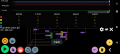
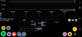
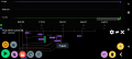
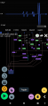
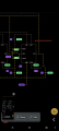
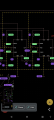
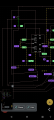
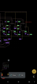
I HAVE THIS CIRCUIT that I have been working on and I'm to a point where I need someone who's experienced and can take a look at my schematic and help me figure out if it ready to build or not. I will credit you as supervise or certified inspector or oversight manager. What ever you want to be credited for you got it I just need some help
 

Attachments

MisterBill2

Joined Jan 23, 2018
19,630
Are those schematic diagrams?? I thought I was seeing PCB layouts.. An actual circuit schematic, with one color of conductors that contrast a white background will work. What ever it was I saw I am not able to identify, much less evaluate.. And if the active devices are indeed 555 timer ICs, the frequency may be OK, but tthe waveform will be of the square wave type, OK for feeding tone-shaping networks, and good for driving digital things and circuits. But not pleasant to listen to.
 

Thread Starter

XINNIX

Joined Feb 24, 2024
5
What about posting the schematics with a white background?

Yours is hard to read.
Sorry it's on an app the background is black, I suppose I can go mess with the screenshots in photoshop for an hour and repost pics, but I'm going to give it a minute and see if anyone else can figure it out without having to do further work that may or may not be helpful in solving my dilemma, but thanks for that advice
 

Thread Starter

XINNIX

Joined Feb 24, 2024
5
Your NE555 IC oscillators sound like buzzers, not like an audio synthesizer.
Is the "speaker" at the bottom of most schematics a piezo squeaker?
I'm using an app called "pronto" & the piatzo is the best representation of a speaker in there symbol library I have requested for them to add a speaker so the ohms in the circuit would make more sense.
What I have done is take the
"atari punk console" ( https://sdiy.info/wiki/File:APC_with_2_555_(pin_out)_and_bridge_added.png )
Except that I'm attempting to use 3 nec555 timer chips instead of the original single chip or the sometimes scene two chip what can also be used is the NEC 556 is like two chips and combined to one I don't know if maybe I should be using four chips to make this more proper what I'm trying to do I'm essentially just trying to get a couple oscillation sounds being driven by the chips so that I can tune them against each other for my oscillator sound and I will multiply that process and drive it to a keyboard and whatever next steps I have to go to but for now it's just to try to use the chips to get three oscillating sounds out of it I'm not sure if I'm taking the right approach or if there's more that I should do I don't know thanks for whatever input you got
 

Thread Starter

XINNIX

Joined Feb 24, 2024
5
Are those schematic diagrams?? I thought I was seeing PCB layouts.. An actual circuit schematic, with one color of conductors that contrast a white background will work. What ever it was I saw I am not able to identify, much less evaluate.. And if the active devices are indeed 555 timer ICs, the frequency may be OK, but tthe waveform will be of the square wave type, OK for feeding tone-shaping networks, and good for driving digital things and circuits. But not pleasant to listen to.
It actually is a pcb software that I'm working with so I don't blow through tons of time and components, with the multiple errors I would make it's called "Pronto" I know the sound isn't the best. Ultimately I want to be able to switch from saw - square - sine on a 3 position switch I will then combine 3 of these circuits to drive the synthesizer I also want to be able to tune the circuit so at the end there will be 3 tunable oscillating circuits comprised of 3 different wave forms in each circuit to drive the synthesizer and whatever additional Parts I'm going to put on it like low pass filter high pass filter EQ that sort of thing. Since everybody here is requested it I'm just going to go ahead and change those images to photoshop I'll try to create a combined image I was only able to capture portion of the circuit because it doesn't allow me to zoom out that far so I'll be reposting maybe in a couple hours from now. Stay tuned and thanks
 

Thread Starter

XINNIX

Joined Feb 24, 2024
5
Why can't you all just answer the questions from the original thread instead of look for ways I'm presenting my question to you
 

MisterBill2

Joined Jan 23, 2018
19,630
Very interesting today!!! I went back and this time I was able to see the circuit much more clearly. But only snippets of a whole circuit.
My understanding now is that the intention is to have a large number of oscillators, each set to a different frequency, and then to select the frequencies to be mixed together through a keyboard. There is nothing so terribly complex about that. What does become tricky is the different wave-forms, because the 555 does not deliver a sine wave at any point.
What I think I see is connections between the different oscillator circuits, That portion is not clear to me, nor is the purpose clear. What I can recommend is that there should be adequate bypass capacitors on the power supply to each device in order to prevent unintended coupling between the individual circuits.
Mixing the selected signals from the keyboard can be achieved through a traditional passive mixer circuit.

I may not have addressed all of the TS concerns, but that is because of the challenge to interpret the circuits ai have seen. I lack the ability to fully interpret what I CAN NOT UNDERSTAND FULLY.
And also I do not pretend to know everything about what I do not know, and can not see.
 

ScottWang

Joined Aug 23, 2012
7,419
Why can't you all just answer the questions from the original thread instead of look for ways I'm presenting my question to you
Wrong input will be get a wrong output.

The members stay here to help you, and they asked you because they want to get the right input from you, and then they can give you the right output, so you should be thank them.
 

MisterBill2

Joined Jan 23, 2018
19,630
A partial answer to the original question is that even when using the dual timer (556) IC, all of the individual oscillators should not be sharing any circuit elements except for the required bypass capacitors. That is because, at least usually, the mixing of signals is restricted to the area where the mixing is intentional and controlled by the user.
As for the possibility of starting out with three waveforms, Sine, Square, and Triangle, that could be done with an 8038 IC, but the circuit is vastly more complex and the IC is more expensive. Filtering is always a possibility, and while I understand the schemes used, I am not prepared to offer advice i that area.
 
Top