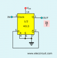
Boat Engine RPM signal divider, Use 4 tacho/revcounter with 8 cylinder engine, simple points style ignition

Thread Starter

LPGC

Joined May 13, 2014
11
Hello forum, I don't remember the last time I posted here.

I have a boat with a V8 engine that I have rebuilt. The revcounter is supposedly switchable to be able to work with 2, 4, 6 and (I believe) 8 cylinder engines. The problem is that the revcounter seems not to work properly when set to what I believe is the 8 cylinder setting. It will work when set to the 4 cylinder setting but of course using the 4 cylinder setting with the 8 cylinder engine means the revcounter reads exactly double actual rpm. This is a problem because the engine redline is 4800rpm and the revcounter only reads up to 6000rpm, so above 3000rpm the revcounter goes off scale and could be damaged by literally bending the needle.

I could buy a gizmo from Amazon that will convert the 8 cylinder engine ignition pulses to work with the revcounter set to 4 cylinders for around £30. The gizmo has dip switches and can be set to convert the tach signal from an engine with just about any number of cylinders to work with any rev counter, but I hope someone on this forum can show me a simple electronics circuit that will do what I need.

Nearly forgot to mention, the boat engine has a conventional old-skool sparks distributor with only one ignition coil and for intents and purposes I believe the ignition system could be considered a points style setup, though it is actually electronic inside the distributor.

All the unit has to do is output 1 pulse to the tacho/revcounter for every 2 ignition pulses (from the negative pulsing side of the ignition coil). I could probably look at other threads (I did check to see if this subject had been covered before) and find a similar circuit to one I'm after, could even maybe design one myself, but I'm not sure about aspects such as whether de-bouncing (for want of a better term) would be necessary for the signal from the ignition coil, or making the circuit to withstand any high voltage pulses from the coil negative (though I suspect this might just involve a high value resistor and a small capacitor)...

Can anyone help please?
 
Last edited:

Thread Starter

LPGC

Joined May 13, 2014
11
Can you remove the tacho and take pictures of the inside, all it will do is alter the pule timings, probably using resistors and capacitor.?
I could but the tacho is part of a car like instrument cluster (on this boat), it is very time consuming to remove it from the dashboard and more time consuming still to disassemble the cluster. I dare say you are correct about the dash cluster / tacho, I have certainly seen resistors, capacitors and IC's inside it... But I would rather pay for the commercial unit than remove and disassemble the cluster again and i doubt anyone reading this will be familiar with this tacho or cluster as it is unique to a 1996 Four Winns Sundowner 205 boat, so I would rather not put it to chance that anyone can suggest an easy fix for the cluster considering it works properly when it is set to 4 cylinder engine mode.

I am hoping someone will post a simple circuit that will convert the 4 ignition pulses per engine revolution of the V8 engine into 2 pulses per engine revolution... Or in other words output half the number of pulses from the ignition coil that it receives. Surely this is very similar to using a momentary switch latch circuit to turn on/off a light bulb but instead of pulses from a switch there are pulses from the (pulsed) ignition coil and instead of the lightbulb there is an output to the tacho... ?
 
Last edited:

Alec_t

Joined Sep 17, 2013
14,425
Depending on where/how the input signal is derived it may also need clamping/attenuating/amplifying/filtering before being used as a clock pulse for a CD4013.
Can you tell/show us how the rev counter gets its input and what voltages are involved?
 
It might be simpler to cheat and put a magnetic pickup coil on two of the single plug wires. and then set the tacho for two cylinders. Or just a simple magnetic pickup to pick up two bumps on the crankshaft belt drive pulley at the front of the engine.
 

Thread Starter

LPGC

Joined May 13, 2014
11
Sorry I'm a little late returning to my thread here, I was under the impression I would receive email notification of new posts.

I was expecting a simpler circuit just involving a few transistors, resistors and capacitors but I bow down to superior knowledge if a more modern circuit involving chip(s) would be neater and/or work better. I'm not familiar with many chips other than basic stuff like 7805/7812 and to a lesser degree stuff like 555's. Just had a quick look at the datasheet for the 4013 and can see now that it has 2 x flip flop's on it which I assume is hence the suggestion.

I don't think the boat tacho will be pulse width sensitive because it will be designed to be accurate even if someone adjusted the dwell angle on old-skool points type ignition (thinking dwell angle, duty cycle of coil earth, pulse width are for intents and purposes synonymous), I believe that (at least to a high degree) the tacho will only be frequency sensitive...

Having said the above I will still ask the question does the output of the circuit posted above by @crutschow maintain state until the input is triggered or does it output a fixed pulse width? Before I realised I had replies on this thread I Googled flip flop circuits and found on another forum someone had tried to do similar to what I'm trying to do and the 4013 had been suggested but when the OP made the circuit there were some issues with the tacho due to output pulse width becoming DC at above around 2700rpm. If the circuit output is just half frequency of input frequency (not a fixed pulse width) that won't be a problem but if the circuit outputs a fixed pulse width I'd need to consider how long that pulse should be.
 

Dodgydave

Joined Jun 22, 2012
11,389
The output of the CD4013 will be half of the signal on the input, so if the pulse width alters on the input, so will the output, it will be a square wave.
 

Thread Starter

LPGC

Joined May 13, 2014
11
It might be simpler to cheat and put a magnetic pickup coil on two of the single plug wires. and then set the tacho for two cylinders. Or just a simple magnetic pickup to pick up two bumps on the crankshaft belt drive pulley at the front of the engine.
The thought did occur to use inductive pickups on 2 or 4 of the plug leads thanks for the suggestion @MisterBill2 . But I think just for intents of getting the revcounter working properly I'd prefer a neater connection in the engine bay.

However, I am still very interested in using inductive pickups on spark plug leads but for a different project...
https://forum.allaboutcircuits.com/...ion-input-for-a-fuel-injection-system.201652/
 

Thread Starter

LPGC

Joined May 13, 2014
11
The output of the CD4013 will be half of the signal on the input, so if the pulse width alters on the input, so will the output, it will be a square wave.
Thanks Dave,

I was expecting that.

I probably don't need to think into this aspect any further... But out of interest (and I think I realise what you mean by square wave), what will be the duty cycle of the square wave? I ask because I believe points (or this electronic ignition module inside the distributor that does the same function as points) have long periods of 'on' to charge the coil up, then a shorter period of 'off' at which point the coil field collapses and causes the high voltage pulse to occur on the output to the the distributor rotor arm. Will the flip/flop do: output a long period of 'on' followed by short period of 'off' then output a short period of 'on' followed by a long period of 'off', loop?

Edit - Thought about this a bit more and think I've answered my own question, no it won't because it isn't reading change of state it is only reading start of on.
 

Thread Starter

LPGC

Joined May 13, 2014
11
Yes , what is the signal from the distributor, have you measured it with a multimeter or oscilloscope?
I do have a basic oscilloscope but I haven't used it for a while and believe it is broken. The last time I used it was a couple of years ago for checking the signal from an engine's crank and camshaft position sensors.

It is just an old skool conventional ignition system, just has the points replaced with an old-skool type points-less system. The ignition coil gets 12v constant battery voltage (with ignition on) on it's +ve connector, a wire coming straight from the electronic ignition inside the distributor runs directly to the -ve of the coil to ground the negative. I originally had a voltage drop to the coil from the ignition switch and suspected a ballast resistor was fitted but that turned out to be just a voltage drop across the 'dead man switch' which I bypassed, the coil gets full battery voltage.

So again as with old skool ignition systems we see +12v on the -ve of the coil when the electronic ignition isn't grounding the coil -ve and close to 0V when the electronic ignition is grounding the coil negative. But I am sure there will be some voltage spikes on the coil -ve.
 
Thanks Dave,

I was expecting that.

I probably don't need to think into this aspect any further... But out of interest (and I think I realise what you mean by square wave), what will be the duty cycle of the square wave? I ask because I believe points (or this electronic ignition module inside the distributor that does the same function as points) have long periods of 'on' to charge the coil up, then a shorter period of 'off' at which point the coil field collapses and causes the high voltage pulse to occur on the output to the the distributor rotor arm. Will the flip/flop do: output a long period of 'on' followed by short period of 'off' then output a short period of 'on' followed by a long period of 'off', loop?

Edit - Thought about this a bit more and think I've answered my own question, no it won't because it isn't reading change of state it is only reading start of on.
The output of the CD4013 changes state on every input pulse, so the output will be a 50% duty cycle square wave at half the input frequency. BUT the output may not be able to drive the tach input adequately. Good news is that the IC CAN operate very well on 12 volts DC.
 
BUT the output may not be able to drive the tach input adequately.
I was wondering about that myself. In the little bit of experimentation I have done I remember one large spike followed by several ripples of decent magnitude on the (-) of the coil where it sounds like this tach would connect to. I don't remember the voltages off hand, but it's well past the normal 13-14 volts you will see in the rest of the system.
 
I was wondering about that myself. In the little bit of experimentation I have done I remember one large spike followed by several ripples of decent magnitude on the (-) of the coil where it sounds like this tach would connect to. I don't remember the voltages off hand, but it's well past the normal 13-14 volts you will see in the rest of the system.
If that spike is big enough to flash a neon bulb, that would work very well to provide optical isolation that could drive a CD4013 directly. But there will still need to be some amplifying done.
Of course, the alternative is to just open a switch and only let every other raw pulse pass thru. That will avoid any amplifier requirements. And it might be a lot simpler. Use another opto-isolator fast transistor and have the CD4013 drive a fast LED to switch the photo transistor switch on and off.
 
Of course, the alternative is to just open a switch and only let every other raw pulse pass thru. That will avoid any amplifier requirements. And it might be a lot simpler. Use another opto-isolator fast transistor and have the CD4013 drive a fast LED to switch the photo transistor switch on and off.
I was trying to think of something along those lines, but my hobby level experience left me blind. It seemed possible, but outside of my experience.

Now I'm curious enough to set up some equipment tomorrow and scope things out. I have a truck with a HEI distributor I can tap into the coil connection and get a waveform to go off of. Granted it's not going to be the same as the OPs engine and probably a bit higher voltage wise, but it will give some base line idea.
 
Top