BCD to dual 7 segment display

Thread Starter

philippe53

Joined May 4, 2014
17
Hi everyone,
I'm working on a project and I need to display a number from 1 to 20.
I would use two separate 7 segment display or a dual one.
The number displayed must be in relation from a BCD code.
I'm looking for the easiest way to do the job, with minimum components.
Could you help ?
Thanks in advance
 

Thread Starter

philippe53

Joined May 4, 2014
17
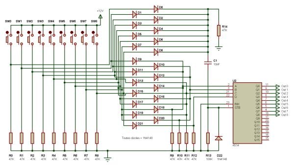
The bcd code is taken from the inputs of a 4514, selected by 15 push button switches via signal diodes; I need to visualize the enabled output (here from 1 to 15, zero is not used). I said 1 to 20 but 1 to 15 is enough.
thanks
 

djsfantasi

Joined Apr 11, 2010
9,163
You know you can display these values in hex format with one 7-segment display? Search for hexadecimal to 7-segment decoder/driver. 10-15 are shown as A-F.

The input to a 4514 is not BCD, but is hexadecimal. Converting from hex to BCD is not-trivial.

What is the purpose of the entire circuit? I can see the display also coming from the input switches via a diode array, or similarly from the output of the 4514. Going from 1 of 15 switches to BCD to 1 of 16 outputs seems redundant. Why not eliminate the two intermediate steps?
 

Thread Starter

philippe53

Joined May 4, 2014
17
The purpose of the circuit : dispaching
On the front pannel, there are 15 momentary push buttons connected via diodes to the 4 adress inputs of the 4514; 15 of the 16 outputs of the 4514 drive, via 2 ULN2804, 30 relays to switch one of the 15 speakers pairs.
Only one of the 15 ouputs can be actived in a time. There are also a temporisation of 250 ms between the outputs of the 4514 and the inputs of the ULN2804 to let some time between the switching of the relays.
I want to drive a double digit (or 2 single digits) to show the pair of speakers which is connected to the amplifier.
I've built an other dispaching with 8 ouputs, and it has a single 7 segments digit to show the output actived. I used a 4543, with her inputs connected to 3 of the 4 input line of the 4514.
 
Last edited:

MrChips

Joined Oct 2, 2009
30,824
What you are requesting is a 15-line to dual 7-segment display encoder.
You can design this with discrete logic.

The easiest solution with minimum components would be a single chip microcontroller.
You will need an MCU with three 8-bit ports (two ports for inputs and one port for the 7-segment display output).

I am sure that there is someone here on AAC who would be delighted to program an MCU chip for you.
 
Last edited:

Thread Starter

philippe53

Joined May 4, 2014
17
I've not experience with MCU... I though some discrete logic to drive a dual display could exist ?
I don't know how to begin with the MCU, as any one some links with examples ?
Thanks

Don't you think a DS8669 2-Digit BCD to 7-Segment Decoder/Driver could do the job ?
 

djsfantasi

Joined Apr 11, 2010
9,163
If you already have the push buttons, diode array and 4514 circuit built, you can reduce the requirements for the MCU to 4 pins (BCD input) and one 8 bit port for the 7 segment displays (multiplexed).
 

ericgibbs

Joined Jan 29, 2010
18,882
I've not experience with MCU... I though some discrete logic to drive a dual display could exist ?
I don't know how to begin with the MCU, as any one some links with examples ?
Thanks

Don't you think a DS8669 2-Digit BCD to 7-Segment Decoder/Driver could do the job ?
hi,
This IC could be used, but the problem it requires two BCD coded bytes.

Have you considered a regular LED for each of the 4514 selected channel.?
You could number them 1 thru 15 on a front panel, the selected channel LED would be illuminated.
E
 

Thread Starter

philippe53

Joined May 4, 2014
17
You could number them 1 thru 15 on a front panel, the selected channel LED would be illuminated.
Yes I can easily do this because the push buttons can be illuminated (they have a little led inside), but I find the dual 7 segment more attractive !
Is there some discrete logic to drive the sealed dual digit display ?
I found this circuit : http://www.thelearningpit.com/lp/doc/7seg/7seg.html
 
Last edited:

djsfantasi

Joined Apr 11, 2010
9,163
The problem is that your input is NOT BCD. It is binary. (I've said hexadecimal before, but that may have confused the issue. To me binary and hexadecimal are similar enough that sometimes I misuse the names when talking about values)

Let's consider push button # 11. Your input to the 4511 is expected to be 1011. This is the binary representation of decimal 11.

However, the BCD representation requires 8 bits. The first four for the ten's digit and the last four for the one's digit in BCD.

Pushbutton #11 in BCD is then 0001 0001.
Similarly, Pushbutton #13 in BCD is represented by 0001 0011.

What you need is a discrete logic solution to that problem. An IC that was used to do that is no longer available. Using an MCU seems to be the most popular method currently. Searches indicates that some have programmed an EEPROM as a lookup table. Other than that, I can't help, as I am in the MCU camp.
 
Last edited:

Thread Starter

philippe53

Joined May 4, 2014
17
However, the BCD representation requires 8 bits. The first four for the ten's digit and the last four for the one's digit in BCD.
Yes you're right, and that's why it's difficult !
And if I drive the "1" of the ten's digit with the 4514 ouputs 10 to 15 (that's easy with some diodes), the one's digits will not give the good number.
But I'm sure there's a way to do what I want without MCU...
I have to convert the 1010 to 0000, the 1011 to 0001, and etc.. but how ?
 
Last edited:

elec_mech

Joined Nov 12, 2008
1,500
I'm looking for the easiest way to do the job, with minimum components.
But I'm sure there's a way to do what I want without MCU...
These two statements are mutually exclusive. As others have stated, you're trying to take a binary value and get two distinct BCD values to drive a dual 7-segment display. Can it be done in discrete logic? Sure, but it will consistent of several IC's and require a good-sized PCB not to mention all the time and trial and error involved. This is not the easiest nor can it be done with a minimum number of components.

I agree with djsfantasi, if you feed an MCU with the BCD output of the 4514, you can reduce the I/O count of the MCU (use a smaller one).

Bite the bullet and let someone program it for you.
I can do this with a PICAXE if you'd like. If you're interested, let us know the size, forward voltage, and current of the 7-segment display you plan to use. Also note an MCU will need 5VDC.
 

elec_mech

Joined Nov 12, 2008
1,500
Elec_mech, I think you meant the binary INPUTS to the 4514. I certainly did.
No, meant the the outputs thinking the OP meant to use the 4514 to convert the 16 binary inputs to BCD output, but I obviously didn't read closely the first time nor understand the function of the 4514 very well:

The bcd code is taken from the inputs of a 4514, selected by 15 push button switches via signal diodes; I need to visualize the enabled output (here from 1 to 15, zero is not used). I said 1 to 20 but 1 to 15 is enough.
Thank you for the diagram, pictures are quite literally worth a thousand words . . . Like the use of the 4532's and the NOT gate to multiplex the two 7-segment digits with one I/O. :)
 

Thread Starter

philippe53

Joined May 4, 2014
17
As an aid to this thread, I've drawn a block diagram as I understand the project at this time. Phillippe53, can you confirm or ask questions about it?
Yes, what you describe is exactly what I do (or want to do for the 7 segments) !
Imagine there are only ten channels, I could use the 4553 to display 1 to 9, and for the "10" I could use some diodes to enable the segments "1" and "0", with the outputs of the 4514. But to display 11 to 15 by this way would use a lot of diodes...
No, meant the the outputs thinking the OP meant to use the 4514 to convert the 16 binary inputs to BCD output, but I obviously didn't read closely the first time nor understand the function of the 4514 very well:
The 4514 has four input lines, selected by the momentary push buttons via signal diodes. 15 of the 16 outputs drive 30 double relays (L+R+L-R-). If you push for example the button 1, the output one is high and taken in memory via the stb as long as an other button is pressed. There are 16 outputs, and 15 used to drive the relays. So you could use the four inputs lines or the 15 outputs lines to drive a double 7 segments digit.

 
Last edited:

elec_mech

Joined Nov 12, 2008
1,500
I'm still scratching my head because I see the schematic you provided, but I don't see 15 switches. Between SW0 to SW8, is only one switch ever pressed at a given time or are multiple switches pressed simultaneously?

The 4553 is a counter, you send it a clock pulse and it advances a BCD output by one which must then go to a BCD-to-7-segment driver IC. It cannot be used to show a specific value as you describe. You could use a 4511 or 4543 for each digit, but to break up two numbers once you reach 10-15, you'd need to do something like recognize the value is more than 9 then perform subtraction, e.g., subtract BCD 13 from BCD 10 to get BCD 3 for the ones place. Again, no simple task to do with discrete logic.

If you're willing to give an MCU a try, you could replace all the diodes with an I/O port expander and use the MCU to detect when and which button is pressed (again assuming you have something in place to prevent the user from pressing more than one button at a given time). You could use another port expander to replace the 4514, however, since since a port expander is about $2 USD, you could stick with the <$1 4514 and connect it to the MCU as well. Up to you of course. This is just one of many options with an MCU route. Are you making just one of these or many?
 
Top