Battery desulphation for lead-acid types - anyone?

Thread Starter

SgtWookie

Joined Jul 17, 2007
22,230
Do any of you have battery desulphators?

I've been doing some research lately on battery desulphation. Seems that when 12v lead-acid batteries fall below about 12.4v, sulphation begins; the formation of sulphur deposits on the lead plates of the batteries. This has the effect of weakening the batteries in two rather direct ways:

1) Decreasing the surface area of the plates, due to being covered by the sulphur.
2) Decreasing the strength of the acid.

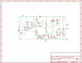
There are off-the-shelf solutions available for a couple hundred bucks (US), but I came across the attached schematic for a rather simple battery desulphator that was devised by an AARL member, WX2NJ (attached, Desulfator.doc). He claims that it greatly extends the life of gel-cel batteries. Since he is an AARL member and has a legitimate call sign, his basic design does bear serious consideration.

I simulated a modified version of his design (with components available in my simulator), and it does seem to work very similarly to what he's posted.

So, without too much more adieu, I've attached an adaptation of his schematic and a board for it (the caps are a bit crowding; they could be moved down a tad.) Those of you with the Eagle Layout Editor can play around with the .brd and .sch attachments. The board is only 2" x 3".

I've added peak voltage and average voltage circuits. Yes, I know the peak voltage will be reduced by the Vf of the diode, and will degrade over time. That's the idea. Basically, you want to add 1 volt to the reading you get; that's the peak voltage. The average voltage circuit is necessary because of the high voltage pulse. One needs to know if the voltage falls to a state that would mean a discharged battery, or a shorted cell. However, battery voltage can't be measured directly when the desulphation process is active.

A charger can be connected at the point indicated, however it must be a low current "trickle" charger, and it must not be powered unless the desulpation circuit is connected to a battery.

Our local Vietnam War Museum has a fleet of vehicles that has batteries which must be maintained. We need them to last as long as possible.

Comments? Suggestions? Whatever?
 

Attachments

Last edited:

beenthere

Joined Apr 20, 2004
15,819
Desulfation seems to be sort of controversial as to how and if it works. I didn't even know it applied to gel types.

The battery charger I posted in the Projects Collection can be adjusted to do a float at 13.2 volts. It might nip the problem in the bud.

Must the batteries be maintained in the vehicles? I've lived in Florida so I know how the heat and humidity gets to everything.
 

Thread Starter

SgtWookie

Joined Jul 17, 2007
22,230
Desulfation seems to be sort of controversial as to how and if it works. I didn't even know it applied to gel types.
Actually, I didn't either. But why would this AARL guy go to the trouble of building a circuit that didn't help the batteries last longer - and they get batteries for free! (I won't post the website; you can find out all about them by Googling for keywords in the .doc file I attached.)
The battery charger I posted in the Projects Collection can be adjusted to do a float at 13.2 volts. It might nip the problem in the bud.
Well, that's the thing - the batteries we have available were on "float" (literally in Navy ships) for over a year as resupply items. They need desulpation.

Must the batteries be maintained in the vehicles? I've lived in Florida so I know how the heat and humidity gets to everything.
You should come down here and see the fleet.
http://nwmvocf.org
7 - M148 Jeeps (two of which are currently operational)
3 - 2.5 ton trucks (one is a "parts donor" truck)
1 - 5 ton truck
1 - PBR (Patrol Boat, River)
1 - Ordinance forklift (I forget the correct designation offhand)
1 - Tracked vehicle (see above)
1 - Avenger (think HMMVEE with a missile launcher mounted on it)

These things have LOTS of batteries in them, and we want to keep them going. Just one Deuce & 1/2 has FOUR 12.6V batteries that are far larger than standard automotive batteries for it's 28v system. We're old farts, and schlepping batteries around definitely isn't very high on our list of priorites. We're looking for an in-situ solution.

OT: BTW, there's a GTG for former Red Crown members here in O-town coming up. Check the Jewett website. I might be able to provide you with a place to stash your seabag.
 
Last edited:

mindmapper

Joined Aug 17, 2008
34
During 30 years I've seen many circuits to do desulpation. If some of them really did work, why don't we se them out there in the shops. It would be a big fuzz of a working one.

My advice is to trickle charge them well above 12.4V, but not higher than 13.2V. Monitor them to se that no one fall below 12.4V. In that case exercise them and charge them again, a number of cycles.
 

jpanhalt

Joined Jan 18, 2008
11,087
As you know, lead sulfate is formed normally when a battery produces power and is converted back to lead and lead(IV) dioxide when it is recharged. (See the thread on PbO2 in the Feedback and Suggestions forum for a draft revision for AAC and more detail.)

The mechanism by which the initially formed, metastable, amorphous lead sulfate converts to a stable crystalline form that is resistant to recharging is poorly understood. Even after 150 years of lead-acid battery use, there is active research in that process and how to delay or prevent it.

I am skeptical of claims made by vendors of desulfators, particularly when they claim magical resonant frequencies are used (too much like some other scams); however, I am not convinced that some type of desulfator might help restore a battery that is not fully sulfated.

I would be very interested in hearing results from a non-conflicted, reliable person like you, SgtWookie.

As for shop lore, it is said that slightly gassing (i.e., over-charging) a lead acid battery will delay sulfation. I suspect the rationale behind that is to reduce to an absolute minimum the amount of lead sulfate in the cells. Of course, if one does that, it is best done in a vented cell, so you can check the fluid levels.

John
 

HarveyH42

Joined Jul 22, 2007
426
There is a forum dedicated to the topic;
http://leadacidbatterydesulfation.yuku.com/directory

I bought this one for $49 (Northern Tools);
http://www.vdcelectronics.com/batteryminder_12117.htm

Only been using it a few months, but revived 3 out of 7 batteries I've hooked up. The 4 failures were completely dead to begin with (2-5 volts). The three I saved wouldn't hold a full charge, but in better shape. Anyway, $50 bucks wasn't a huge amount compared to a new battery, figured if it saved a few great, if not, it'll still charge and maintain a trickle...
 
Hi Sgt Wookie,


I have researched several circuits with the intent to find most reliable and versatile unit. You posted a schema of the one by WX2NJ. It is very similar to the N-channel unit by Alastair Evans
I like it's peak V, avg V capabilities. Could you please let me know how did you get the board?

Have you ever seen Ron Ingraham's version? I can not find it anywhere.
Thanx
 

Thread Starter

SgtWookie

Joined Jul 17, 2007
22,230
Hi Sgt Wookie,

I have researched several circuits with the intent to find most reliable and versatile unit. You posted a schema of the one by WX2NJ.
Actually, I did start with WX2NJ's schematic, and I should have mentioned him in the original thread. :(
The link to his page is here:
http://home.comcast.net/~wx2nj/aresbox.html
On that page, the link to his Word-format schematic and parts list:
http://home.comcast.net/~wx2nj/Desulfator.doc#Desulfator Schematic
It is very similar to the N-channel unit by Alastair Evans
I like it's peak V, avg V capabilities. Could you please let me know how did you get the board?
I added those features, and did the board layout as an experiment using Cadsoft's Eagle Layout Editor. I'm not happy with the layout; the signal paths are too long and convoluted. I put that project on hold for a bit while considering a microcontroller driven solution.

Have you ever seen Ron Ingraham's version? I can not find it anywhere.
Thanx
Ron Ingraham's schematic is linked to on this page:
http://home.comcast.net/~ddenhardt201263/desulfator/lowpower.htm
Ron's schematic uses an IRFZ44, which does not have a high enough voltage rating (55v). WX2NJ's circuit uses an NDP7061, which only has a 60v rating. One item that none of the desulphator circuits has (including mine) is a Zener to clamp the maximum output voltage in case of a badly sulphated or defective battery. As things are now if the load is high impedance, the MOSFET would get "zapped" due to high voltage in the output.

I'd decided on an IRF730, which will withstand 400 Vdss, yet pass 5.5A current when on. An IRF630 or the like with a Zener clamp would probably work better.
 
IRF 740 would work even better, Vdss= 400V, Id=10A, dv/dt=5.9
and perhaps SPP11N60S5 would be better, Vdss=600V, Id=11A,dv/dt=20.
Add a varistor for FET protection, VDRS20W175 ?

?Some diagrams have pin 5 of the LM555 open; other show 10 nF cap to the ground. By omission? What is right?
 
Top