basic high side mosfet driver help!

Thread Starter

shortbus

Joined Sep 30, 2009
10,045
First off, THANK YOU, to all the people that make this site so GREAT!!!
Theres a real wealth of knowledge here!

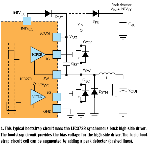
Now my questions. I've researched and read every thing I can find about high side high voltage mosfet drivers I can find. Found out how to calculate the capacitance rating, but, what about the Voltage rating? Its not mentioned anywhere I could find.

One side of the Cbst(C boot strap) is tied to the Vcc of the ic, usually 15VDC. But the other side of Cbst is tied to VS or the source of the mosfet, which can be as high as 600Vdc on some drivers.

So, what Voltage capacitor do you pick for Cbst?

What diode to use for Dbst?

Please help me out, Cary
 

SgtWookie

Joined Jul 17, 2007
22,230
Hi Gary,
Basic "rule of thumb" is double the voltage. If your Vs is 500v, use a cap and diode rated for twice that.

You might get away with using a cap & diode rated for slightly less, but the capacitor leakage rate increases dramatically as it nears it's rated voltage. That leads to dissipation of heat; if there's enough heat the cap will fail (sometimes explosively).
 

Thav

Joined Oct 13, 2009
82
The maximum voltage across the capacitor will be almost Vdd. When the low side FET is on, the one side of the cap is connected through it to ground, the other side of the cap will be charged through the bootstrap diode. Then when the low side FET turns off and the high side FET turns on, the low side of the cap will move up to Vdd, and the high side will end up at 2Vdd, so the voltage across the cap will be at most Vdd.
 

Thread Starter

shortbus

Joined Sep 30, 2009
10,045
Thank you both for your replies!.

But this is why I'm having so much trouble wrapping my head around this!!!

Sgt.Wookie, you say twice Vs (in my case it's 100VDC)

Thav, you say Vdd (in my case 12Vdc)

In none of the other posts on this forum or any of the other forums on the Web. Or any of the schematics I've found that use a HS-HV driver show the voltage value.

I would like to use either a IR2110 http://www.irf.com/product-info/datasheets/data/ir2110.pdf or a FAN7371 http://www.fairchildsemi.com/ds/FA/FAN7371.pdf because I already have them.

The IR2110 is a independent high and low side driver (not a half bridge)and i don't need the low side. So using that, how would it recharge with no low side mosfet?

Please be patient with me! Although I'm new to electronics I'm not new to electricity. I can wire a house or car or a machine tool(pre CNC). I never realized how hard it would be to catch on to electronics!!!

thank you, Cary
 

Thav

Joined Oct 13, 2009
82
Ah, I was assuming a certain schematic where your Vdd and high side FET drain voltage were one in the same. If your logic voltage and power voltage are different it complicates things.

The voltage across the capacitor should be Vdd of the driver chip minus the low side FET's source voltage. Basically in this diagram...

if your chip ground is separate from your FET ground you would get a different answer than Vdd.

You do need the bottom side FET to recharge the boost cap. I think we discussed this in the other thread you posted about the FAN7371 in the Electronic Resources forum.
 

Thread Starter

shortbus

Joined Sep 30, 2009
10,045
Ah, I was assuming a certain schematic where your Vdd and high side FET drain voltage were one in the same. If your logic voltage and power voltage are different it complicates things.

The voltage across the capacitor should be Vdd of the driver chip minus the low side FET's source voltage. Basically in this diagram...

if your chip ground is separate from your FET ground you would get a different answer than Vdd.

You do need the bottom side FET to recharge the boost cap. I think we discussed this in the other thread you posted about the FAN7371 in the Electronic Resources forum.[/QUOTE

I started a new thread because we never discussed anything but figuring Cbst value:rolleyes:

In the diagram shown, won't the lower mosfet source be 0 Vdc?

If i need to use a lower mosfet to recharge Cbst, can I just use it to switch on a high(say 1MΩ) resistor from Vsw to ground?

Thank you for helping. Like I said I'm having a hard time understanding this. But I want to learn and one day be able to help out on this site!

Cary
 

Thav

Joined Oct 13, 2009
82
I started a new thread because we never discussed anything but figuring Cbst value:rolleyes:

In the diagram shown, won't the lower mosfet source be 0 Vdc?

If i need to use a lower mosfet to recharge Cbst, can I just use it to switch on a high(say 1MΩ) resistor from Vsw to ground?

Thank you for helping. Like I said I'm having a hard time understanding this. But I want to learn and one day be able to help out on this site!

Cary
Yes, zero in the diagram shown. I was at work and didn't have enough time to put together a diagram that made more sense.

Charging through a resistor won't work. You need current to flow through the FET to be able to charge the boost cap.
 

Thread Starter

shortbus

Joined Sep 30, 2009
10,045
I went back to IRF's website and spent several hours(I'm retired) reading a lot of stuff over again. Then I stumbled on this, and had a "AH-HA" moment. http://www.irf.com/product-info/audio/classdtutorial.pdf
page 17.

That shows the flow of current through the boot strap in a way that I could understand.

More reading and I found this; http://www.irf.com/technical-info/designtp/dt92-4.pdf From this I figured out that you don't really need a lower mosfet, just a way to connect Vs to ground when the upper mosfet is off.

this; http://www.irf.com/technical-info/designtp/dt98-2.pdf states that as long as the load is tied to ground (not into another circuit) the source from the high side mosfet will let Cbs recharge when high side mosfet is off.

Cary
 

Thav

Joined Oct 13, 2009
82
this; http://www.irf.com/technical-info/designtp/dt98-2.pdf states that as long as the load is tied to ground (not into another circuit) the source from the high side mosfet will let Cbs recharge when high side mosfet is off.

Cary
Yes, now that you mention it, this is true. I don't know what exactly your load is, but depending on what it is the boost recharge might be slower than what you could achieve with a lower device.

If the load is inductive you could possibly charge the boost cap over Vdd unless you clamp the load voltage to ground with a diode.
 

Attachments

Top