Automotive project help. Retaining polarity on a switching polarity circuit

Thread Starter

delox

Joined Apr 14, 2022
4
Hello all. Long story short, I am installing some seats from a newer car into a 60's mustang. The new seats have heating and cooling using a canbus controller. I will not be using the canbus, but would like to wire up the heat/cool to work on a switch. I am an electronic circuits amateur.

The system is comprised on a blower motor to move the air through the seats, and a TED to either heat or cool the air. I would ideally like to have a single (DPDT) switch on each seat which can turn on either heat or cool. The blower motor must retain constant polarity to blow in the right direction, while the TED must be reversed to swap from heat to cool.

One catch, the voltage is being stepped down from 12v to 8v through a transformer for the motor and the TED. I would prefer not to have a second transformer in each seat to make this work if possible.

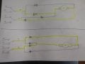
So, I would like to use the DPDT to swap polarity of the circuit, but maintain polarity to motor. I came up with a quick idea with diodes, then tested it with circuitlab and it appeared to work... Am I completely off base or making this too complicated?
 

Attachments

crutschow

Joined Mar 14, 2008
34,408
You should only need the DPDT switch.
What turns on the heating/cooling?
Can't that directly power the fan?
I see no reason to power the fan from the DPDT switch.
 

Thread Starter

delox

Joined Apr 14, 2022
4
Sorry, I should have clarified. The drawings were just a simplified circuit of my plan to force the motor to have a single polarity input. I left out the TED and transformer. The fan and the TED are also designed to only see 8v each.

In actuality, the circuit would go:


12v source >>> DPDT >>> Transformer >>(split)vvv>>> Motor Diode Circuit shown above (fan)
....................................................................................................TED
 

djsfantasi

Joined Apr 11, 2010
9,160
Sorry, I should have clarified. The drawings were just a simplified circuit of my plan to force the motor to have a single polarity input. I left out the TED and transformer. The fan and the TED are also designed to only see 8v each.

In actuality, the circuit would go:


12v source >>> DPDT >>> Transformer >>(split)vvv>>> Motor Diode Circuit shown above (fan)
....................................................................................................TED
First, you cannot use a transformer to change a DC voltage. They only work with AC.

You could use a voltage converter module rated sufficiently to drive the motor. And you’d have to include additional circuitry to protect against the back EMF produced when stopping or reversing the fan. Also, I’d consider a DPDT center off switch. Using a DPDT alone requires that you stop the fan somehow before changing direction. Not absolutely require, but not doing so may damage the fan motor.
 

Thread Starter

delox

Joined Apr 14, 2022
4
Okay sorry wrong term. Not a transformer then, its a step-down module. This is what I'm referring to: https://www.amazon.com/gp/product/B07RBKVDHW/ref=ppx_yo_dt_b_asin_title_o00_s00?ie=UTF8&psc=1 (Dc-Dc Converter 20A 300W Step Up Step Down Buck Boost Power Adjustable Charger Board Module)

And yes, the plan is a DPDT with center-off position. As for reversing the fan, that's the opposite of my intention. I want to keep the fan going the same direction while reversing the TED.
 

djsfantasi

Joined Apr 11, 2010
9,160
As expected, I was complicating it beyond need and there seems to be an obvious solution here.
If a 1.5V drop is acceptable, simply feed the fan from a bridge rectifier. The reversing polarity source attached to the AC inputs and the fan is driven from the DC outputs.

One part. Very simple.
 

BobTPH

Joined Jun 5, 2013
8,938
You could use a 3PDT switch if you could find an appropriate one. Use the 3rd pole to supply power to the fan in either position.
 

shortbus

Joined Sep 30, 2009
10,045
From what I know those heat/cool seats work with PWM to provide a lower voltage. While it looks like a lower voltage on a meter it is really a pulsing 12V(13.5 -14.5 when engine is running). Don't think it comes from a DC-DC convertor, because that would be steady DC when the peltier is expecting to see pulsing DC.
 
Top