Auto Triggering of Timer

Thread Starter

abuhafss

Joined Aug 17, 2010
307
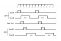
I attach a flow chart of my project.

JOB 1 and JOB 2 are identical processes.
All timers are proposed to be 555/monostable.
JOB 2 will be completed 10 sec after JOB 1.
And then the cycle will be repeated, thus there will be an interval of 10 sec between each job.

Questions:
1) How one timer (Timer A) will trigger the next timer (Timer B)? I mean how will I connect Timer A with Timer B?

2) Studying the flow chart, can somebody guide me if I am correct. And do I need any improvement in the usage of the timers?
 

Attachments

Bernard

Joined Aug 7, 2008
5,784
How I read:
Job 1 takes 5 sec; Job2 takes 15 sec ; Jobs follow each other with 10 sec space between each job. Use 4 555's or 2 556's to make a ring counter.
Tie all resets together & gruond at start, then ground first 555 pin 2 to start operation.
 

Attachments

Thread Starter

abuhafss

Joined Aug 17, 2010
307
How I read:
Job 1 takes 5 sec; Job2 takes 15 sec ; Jobs follow each other with 10 sec space between each job. Use 4 555's or 2 556's to make a ring counter.
Tie all resets together & gruond at start, then ground first 555 pin 2 to start operation.
Maybe you have understood my flowchart correctly, still I clarify:

Job 1 = Process A (5 sec) + Process B (15 sec)
Job 2 = Process AA (5 sec) + Process BB (15 sec)
And the jobs follow each other with 10sec gap.

a) There are 5 timers.
b) Timer A, 5 sec.
c) After 5 seconds, Timer A will trigger Timer B and the delay Timer simultaneously.
d) The delay timer will trigger Timer AA after 5 seconds.
e) Timer AA will trigger Timer BB after another 5 seconds.
f) And finally the Timer BB will re-trigger Timer A after 15 seconds.

Your illustrated help shall be appreciated.
 
Last edited:

Bernard

Joined Aug 7, 2008
5,784
Is it correct to say that the start of process B follows the start of process A by 10 sec.? In other words , the processes overlap? ; or is the 10 sec delay at the end of B to the start of AA?
 

Thread Starter

abuhafss

Joined Aug 17, 2010
307
Is it correct to say that the start of process B follows the start of process A by 10 sec.? In other words , the processes overlap? ; or is the 10 sec delay at the end of B to the start of AA?
No. Simply, the duration of each JOB is 20 seconds. JOB2 starts 5 seconds after JOB1 and another 5 seconds delay is forced. JOB1 and JOB2 executes with a gap of 5 + 5 = 10 seconds. As soon as the JOB2 finishes it re-starts JOB1 and the cycle is repeated. Hence, one job is finished 10 seconds after the other.

1) Timer A finishes Process A in 5 seconds
2) then Timer A triggers Timer B + delay Timer
3) the delay Timer triggers Timer AA after 5 seconds
4) Timer B finishes Process B in 15 seconds and then no more process
5) Timer AA finishes Process AA in 5 seconds
6) then Timer AA triggers Timer BB
7) Timer BB finishes Process BB in 15 seconds
8) then Timer BB re-triggers Timer A (to repeat the cycle)

By the way, could you please guide me how to connect one monostable timer to another such that the 1st timer, after completing its time period, triggers the 2nd one.
 
Last edited:

dasraiser

Joined Sep 1, 2010
5
hi it may help if u draw a time graph showing A/B/transfer-delay/AA/BB, also i think u may only need 3 555timers, 2 set up as pwm utilising sink/source and one for the A:B to AA:BB time delay.
 

Bernard

Joined Aug 7, 2008
5,784
I think this fits your nice timing chart: Five 555's only showing triggering. Still need to tie all resets together & connect to +V via 1k. A momentary short of pin 4's to ground will reset all 555's. Heavily loading of outruts may effect operation.
 

Attachments

Bernard

Joined Aug 7, 2008
5,784
Looks good. I would raise the start SW 2k resistor to 100k [ 10k to 1M] as there is only a + 33% marginal set pulse for timerA as shown. I would also add 1k resistors between pot and pins 7 to prevent accidental connecting Vcc to pins 7 via pot setting. Looks like all 555s should come up reset on power-up.
 

Thread Starter

abuhafss

Joined Aug 17, 2010
307
I would also add 1k resistors between pot and pins 7 to prevent accidental connecting Vcc to pins 7 via pot setting. Looks like all 555s should come up reset on power-up.
I am sorry but, what is POT?

By the way, one friend has advised me that "15 second period generated with a 555 is not likely to be very stable" so I should go for ICM7242 or for some PIC. What do you say?
 

Bernard

Joined Aug 7, 2008
5,784
POT= potentiometer = variable resistor, or your 1M with arrow pointing at it. My one finger typing tends to make mistakes on long words, so ' tend to avoid them where possible. What are your timing accuracy requirements? Persional openion: 15 sec with 555 good for 1% or better. If far greater accuracy is needed, use a master clock, line frequency [ 50 or 60 Hz divided down to 5 sec] or crystal controlled clock driving a counter like 4017 & using gating to derive time periods. Or use 555 divided down, where a smaller cap with low temperature coeficient can be used.
 

Thread Starter

abuhafss

Joined Aug 17, 2010
307
POT= potentiometer = variable resistor, or your 1M with arrow pointing at it. My one finger typing tends to make mistakes on long words, so ' tend to avoid them where possible. What are your timing accuracy requirements? Persional openion: 15 sec with 555 good for 1% or better. If far greater accuracy is needed, use a master clock, line frequency [ 50 or 60 Hz divided down to 5 sec] or crystal controlled clock driving a counter like 4017 & using gating to derive time periods. Or use 555 divided down, where a smaller cap with low temperature coeficient can be used.
Thanks for the details. I got it.
The time accuracy is not so important here, 1-5% tolerance will be no problem.
 
Top