
First time post. I've been googling and reading up on other automotive forums for the past few weeks and I've found a lot of tutorials and how-to's...but they don't get too in depth on the electrical parts side. I've had a few electronics classes, so I think I know enough to get started, but I need some help to finish.
My goal is to create a fan controller that will be rock solid that will not break down in 2 years when I'm on the highway.
Background: I have a Ford Ranger that has been pretty good, but has the 3.0L engine that is a bit underpowered. There has been a bunch of guys that will buy kits and be on their way, but they use probes that they stick in the radiator with an adjustable on/off controller. I just don't like the idea of using a setup that other automotive manufacturers won't use.
So using what I've found online, I think I've come up with this design:
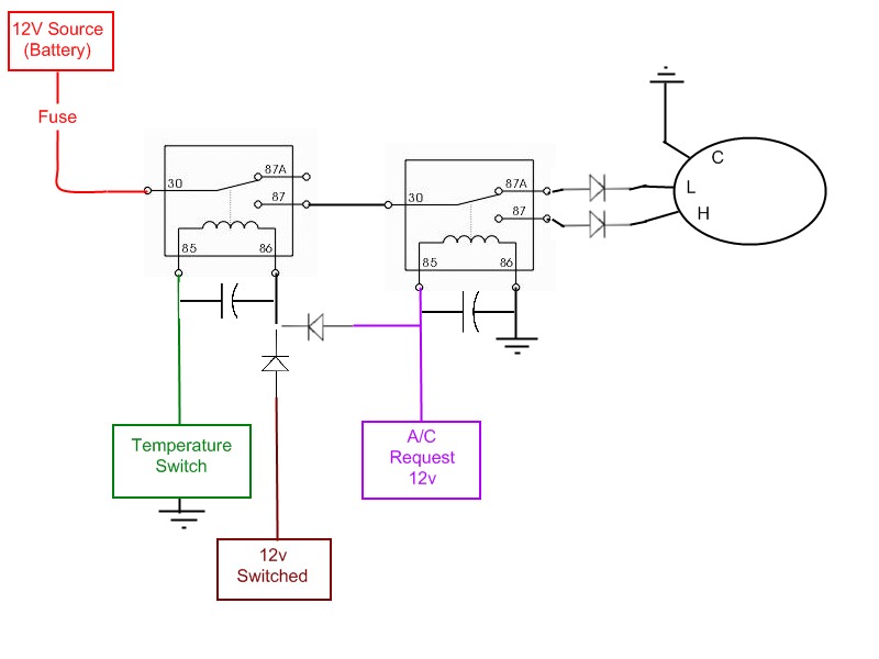
A little explanation on what's going on. Going left to right, I have the truck battery going to a relay. This relay is the on/off for the whole system. It is controlled by one of two signals. A temperature switch that has a high resistance until 200 degrees. Once 200 is reached, resistance is lowered allowing electrical flow energizing the relay coil. Once fans cools the engine until 185 degrees, resistance goes back up, stops electrical flow, and the coil de-energizes. No matter what temperature the engine is at, if the Air Conditioning is turned on, the first relay must be turned on. I had initially thought of diodes to connect both 12v switched and A/C Request, but after reading a bit on here..I could use a transistor or even another relay...but I'm not sure what would be better.
Past the first relay, the second relay basically switches the output for the fan motor. The fan is a 2-speed with three wires: ground, low speed, high speed. This relay is controlled only by the A/C Request. The fan is more than enough power to cool the engine on low, but when the AC is on, high speed should be selected to get more air past the condenser lines.
The fan is supposed to pull less than 20 amps on low. On high, it pulls about 30-40amps when up to speed, while getting up to speed, it is said to pull upwards of 50-60. I have yet to find hard information on the fan. This fan is found in Ford Taurus cars and Lincoln Mark-VIII cars.
So that's how I want it to work, but here are a few things I'm unsure about.
1) I've read that a capacitor over the coils of a relay is supposed to help protect the relay. I'm sure you guys know this, but how big of a capacitor are we talking about? I've tried reading up on the types of capacitors, but I still can't get a handle on which type would best suit this application.
2) To allow either 12v switched or the A/C Request line to run the first relay, what would be the most cost effective way? I could throw a small relay in there. I think a transistor of some sort would work, but wouldn't know how big of one to use. Diodes may work, but again, not sure of size or type.
3) I've also read a free-wheeling fan motor, when not consuming power, will generate electricity. Some have put diodes on the fan lines to keep the electricity from going back into the controller. Is this really necessary? If the first relay is off, both of the fan's power cables are in a not connected state, so there wouldn't be anywhere for the power to flow, other than through the relay contacts.
4) Since the high-speed setting consumes so much, some people have been buying 75amp relays, but they are 20 bucks each. 30/40 amp relays can be had for about 5-8 bucks. Would adding a capacitor between relay #2 lead 87 and the diode act as a buffer so that when the initial draw happens for high speed, it does not pull so much power through the relays all at once? How would I size that? On a 12v system, would I have to worry about the time it takes to charge up the capacitor?
My goal is to create a fan controller that will be rock solid that will not break down in 2 years when I'm on the highway.
Background: I have a Ford Ranger that has been pretty good, but has the 3.0L engine that is a bit underpowered. There has been a bunch of guys that will buy kits and be on their way, but they use probes that they stick in the radiator with an adjustable on/off controller. I just don't like the idea of using a setup that other automotive manufacturers won't use.
So using what I've found online, I think I've come up with this design:
A little explanation on what's going on. Going left to right, I have the truck battery going to a relay. This relay is the on/off for the whole system. It is controlled by one of two signals. A temperature switch that has a high resistance until 200 degrees. Once 200 is reached, resistance is lowered allowing electrical flow energizing the relay coil. Once fans cools the engine until 185 degrees, resistance goes back up, stops electrical flow, and the coil de-energizes. No matter what temperature the engine is at, if the Air Conditioning is turned on, the first relay must be turned on. I had initially thought of diodes to connect both 12v switched and A/C Request, but after reading a bit on here..I could use a transistor or even another relay...but I'm not sure what would be better.
Past the first relay, the second relay basically switches the output for the fan motor. The fan is a 2-speed with three wires: ground, low speed, high speed. This relay is controlled only by the A/C Request. The fan is more than enough power to cool the engine on low, but when the AC is on, high speed should be selected to get more air past the condenser lines.
The fan is supposed to pull less than 20 amps on low. On high, it pulls about 30-40amps when up to speed, while getting up to speed, it is said to pull upwards of 50-60. I have yet to find hard information on the fan. This fan is found in Ford Taurus cars and Lincoln Mark-VIII cars.
So that's how I want it to work, but here are a few things I'm unsure about.
1) I've read that a capacitor over the coils of a relay is supposed to help protect the relay. I'm sure you guys know this, but how big of a capacitor are we talking about? I've tried reading up on the types of capacitors, but I still can't get a handle on which type would best suit this application.
2) To allow either 12v switched or the A/C Request line to run the first relay, what would be the most cost effective way? I could throw a small relay in there. I think a transistor of some sort would work, but wouldn't know how big of one to use. Diodes may work, but again, not sure of size or type.
3) I've also read a free-wheeling fan motor, when not consuming power, will generate electricity. Some have put diodes on the fan lines to keep the electricity from going back into the controller. Is this really necessary? If the first relay is off, both of the fan's power cables are in a not connected state, so there wouldn't be anywhere for the power to flow, other than through the relay contacts.
4) Since the high-speed setting consumes so much, some people have been buying 75amp relays, but they are 20 bucks each. 30/40 amp relays can be had for about 5-8 bucks. Would adding a capacitor between relay #2 lead 87 and the diode act as a buffer so that when the initial draw happens for high speed, it does not pull so much power through the relays all at once? How would I size that? On a 12v system, would I have to worry about the time it takes to charge up the capacitor?

")


