Your extremely simple circuit is missing a speaker. So it has no power supply and has no load. Connect an 8 ohm speaker in parallel with the oscilloscope and see what happens.
The speaker and the second transistor will get hot.
An osciloscope has most times an input resistance of 1 M or higher.
You are testing the circuit with this resistance.
Try a resistor of 1K accross the inputs of the scope and see what happens.
An osciloscope has most times an input resistance of 1 M or higher.
You are testing the circuit with this resistance.
Try a resistor of 1K accross the inputs of the scope and see what happens.
I think then OP say a scope he/she is refering to a virtual scope in the software
Edit: I also think the OP should apply some voltage to the transistor base bias network. Something is wrong with the schematics
thank you soo much Hobbyist now the only problem left is that my signal at channel B is not amplifying, I mean its amplitude is same as the signal at channel A, how I should increase the amplitude of the output signal???
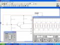
Here is your circuit, with the same values you used, note the 10 ohm collector resistor, and all the settings on the osciloscope, and functrion generator. As well as the circuit configuration.
Notice that the extremely simple class-A "amplifier" has a voltage gain of only 10.
If you use a microphone then you must add a preamp with a voltage gain of about 20.
ok one more question if you can see in the diagram the input signal and output signal are out of phase, what should i do to make the phase of both the signals same???
hey guru I have to show the waveform first to my professor and then my job will be to implement this circuit on bread board and I will have to use mic as input signal and speaker as output, so tell me how many ohms speaker I should select and which type of mic???


")