Assistance Requested - Kenwood KA 3500 - Resistors Running Incredibly Hot but Output Sounds Ok

Thread Starter

olso2231

Joined Jul 4, 2016
7
Hello Community,

This is my first post, so please let me know if this is in the incorrect area of the forum, etc. I'm excited to become part of the community!

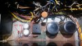
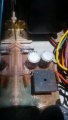
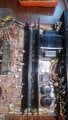
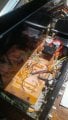
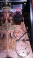
I'm working on restoring an old Kenwood KA 3500 integrated amplifier - so far so good...all of the pots have been cleaned and all of the circuits appear to be working as prescribed except for two resistors on what appears to be the power supply (visually) but seem to be on the output (connected to speaker terminals - per schematic)

http://www.hifiengine.com/manual_library/kenwood/ka-3500.shtml - schematic I posted online.

For some reason, resistors R55 and R57 are running hot...like, crazy hot (R55 running around 500F, and R57 around 160F!)...I'm certain they are fried at this point. What I'm wondering is if due to being old, there was possibly drift that increased the resistance for these and eventually caused them to overheat and fry, which further increased how hot they are running, or if something else may be going on? The amp sounds really good and does not appear to be distorting, etc.

I'm not very familiar with this topology - as I said above, the resistors are physically located in the power section (not power amp section) of the amp, but are evidently linked to the output ....which is odd to me. I have never worked on am amp where the power supply was so directly linked to the output...

I have access to a 30meg scope and dvm, but no signal generator...wondering what my next steps should be in troubleshooting. Any help would be most appreciated. Thank you all in advance!
 

crutschow

Joined Mar 14, 2008
34,467
Those may be bias resistors for the output stage.
Can you locate them on the service manual diagram? (I can't download it since it wants me to register).
Can you measure their resistance?
What is the DC voltage across them?
Are there any adjustment pots on the circuit board?
 

MrChips

Joined Oct 2, 2009
30,824
Your next step would be to get out the DVM and measure the voltages across R55 and R57.

On top of that, measure the voltage on each leg of R55 and R57 with respect to GROUND.
What is GROUND? Try the chassis for starters or the ring on the PHONES Jack.
 

Thread Starter

olso2231

Joined Jul 4, 2016
7
Shoot! Thank you, @bertus, I didn't actually take note of that! Dah! I had assumed they were Re...but they may be Rd...

I'm at work but will try to take a look tonight. I suspect they are Re due to them appearing to be 1 W resistors.

@crutschow - there are two variable resistors on the main amp - I haven't adjusted them yet due to the service manual being slightly unclear. "Bias Adjustment, - Before adjustment, check the power amp has no signal. And then connect the bias current meter (B31-0125-05) across the emitter resistors 0.47 Ohms of the power transistors. Turn the PC trimmer potentiometer 1k ohms until the meter indicates 40mV." - I wasn't sure what other settings were needed...max volume/minvolume, load/no load, etc. Each amp bias seems to be unique. Several that I have done in the past have been max volume, no load...not sure that is the case here.

@MrChips - I'll try to take some readings soon!

Thank you all!
 

bertus

Joined Apr 5, 2008
22,278
Hello,

The powerstage has e as extention.

The resistors Re45 Re46 Re47 and Re48 are 0.47 Ohms 3 Watt.

KA-3500_powerstage.png

It looks like Re55 and Re57 are in the power lines and are 390 and 1K8 ohms.

Bertus
 

DGElder

Joined Apr 3, 2016
351
I would replace the filter capacitors in the power supply as a matter of course, assuming they are the originals electrolytics they are well past operational life. Temperature of 160F is not hot, 500F is quite hot but is still in the operating parameters of some power resistors. I don't know what the deal is with these since I can't see the type or how they are used.

Can you post an image of the schematic so we don't have to register at some site to look at the service manual?

edit: OK, thanks bertus. Re55 should only be running at 1/2 rated power, 500F is way too hot for this 1W resistor so yes something is wrong.
 
Last edited:

Thread Starter

olso2231

Joined Jul 4, 2016
7
Alright - despite nasty storms taking out most of the power in my neighborhood last night, I emerged unscathed. That said, I was able to complete a few tests on R55 and R57. I apologize, the board itself does not specify which extension the resistors are...but the images may help!

R55 had 40 VDC across it while operating - VAC were cycling from 30 to 0…in roughly a 3-4 second timeframe…the lag may be due to my DVM…

R57 had 12.15 VDC across it while operating - VAC were 15.0.

In reference to the picture labeled, “KA3500 Power Supply” – the following measurements were taken with one probe on the case and then the other at each specified area:

“Top” of R57 – 13.0v DC

“Bottom” of R57 – 0.741 VDC

“Top” of R55 – 163.8 mVDC

“Bottom” of R55 – 39.3 VDC

Resistance across each was with the power off on the amp

R57 – 1.793 kOhms

R55 – 0.800 kOhms (this decreased however…suspecting that with the amp off the resistor was cooling off, decreasing resistance [this was the one that was running at 500 degrees F])

One other thing I checked was VDC across the speaker terminals…figured that they really shouldn’t have any due to VDC damaging voice coils relatively easily. There were a few mVDC across each…not much, so this may be ok.

Thoughts?

Also, I am not sure what the green corrosion is from on the board...possibly those jumper wires? They appear to be intact.
 

Attachments

Last edited:

DGElder

Joined Apr 3, 2016
351
olso;

The voltage at the top of Re55 is obviously a problem - it does not match service manual reference voltage and drives the resistor way beyond rating.

I would start at the input of this power section and work out toward the problem area. The filter caps are the most likely to be the problem - that green stuff is from leaking capacitor/s; failures there could then damage other parts such as Re55. Anyway start with AC at points 13 and 14 going into the bridge, check the output of the bridge, check the voltage across each of those input caps (should be the same) and then check voltage across each cap at the output of the bridge(should be the same): i.e. check Ce27, Ce28,Ce29, Ce30 and Ce31, Ce32; check diodes De5 and De6 with power off and caps discharged.

The points between the two input and output capacitors of the bridge are common and should be neutral - maybe tied to ground somewhere, the same is true between the zener diodes. Input 11/12 ground? The output of the bridge should be about + and - 24.5V DC

Anyway, as I said in my original post, you should replace all those electrolytic capacitors in the power section anyway as a matter of course. And Re55. What hasn't failed or become substandard will become so soon.

PS: don't adjust any bias pots or anything else until the unit has been refurbished.

Good luck, a nice amp worth the effort. I gave mine to my nephew a few years back and he says it is still sounding great, but I probably should recall it for a look inside.
 
Last edited:

Thread Starter

olso2231

Joined Jul 4, 2016
7
Thank you, DGElder - this is fantastic! That completely makes sense about the corrosion - I should have explored that more...the unit was sitting in a pole-barn unused for probably 15 plus years so I just attributed the corrosion to condensation/temperature fluctuations.

I have heard that almost any re-ferb is worth swapping all caps in the PSU. While I am swapping caps, would it make sense to over size these or go as close to spec as possible?

Thank you again - this is most appreciated. I'll post more as I work through.
 

DGElder

Joined Apr 3, 2016
351
Thank you, DGElder - this is fantastic! That completely makes sense about the corrosion - I should have explored that more...the unit was sitting in a pole-barn unused for probably 15 plus years so I just attributed the corrosion to condensation/temperature fluctuations.

I have heard that almost any re-ferb is worth swapping all caps in the PSU. While I am swapping caps, would it make sense to over size these or go as close to spec as possible?

Thank you again - this is most appreciated. I'll post more as I work through.

Match the capacitance, if you can't get an exact match go with a little higher cap with equal or less ESR. Also note max temperature and of course voltage rating should be same or higher. Given the age of the unit I wouldn't worry about life rating if it is a name brand.

Note: Re57 is operating well within power rating, what excess heat it has is radiated from Re55 which is sitting right next to it. Of course after you replace these parts you need to check the voltages again.
 
Last edited:

Thread Starter

olso2231

Joined Jul 4, 2016
7
Update - I removed the two caps last night...was a bit surprised to find that they have three leads. From what I have seen, these are either double caps or may just have a third lead "for support". Can't say I have ever run into this before.

I am not necessarily believing that the lead is only for support, as it appears that each lead is tied into the traces on the board and not just randomly placed for support as the forum below describes... However, I have not removed all of the other leads from the board to completely remove it [the board] from the chassis and have a closer look; I have only lifted the board up enough to remove the soldering.

http://audiokarma.org/forums/index.php?threads/6800uf-42-volts-cap-question-ka3500-kenwood.28149/

Ideas?

[edit] - technically the schematic shows that a standard, two lead device should work...
 

Attachments

Last edited:
A note about Biasing.

Generally no signal input. But I also tend to look at the voltage between the two bases of Q17 and Q19. 0 isn't good. I think it should be around 2.4 V in this amp and vary with the bias adjustment. If you have zero, you'll have crossover distortion.

They are nice and tell you to have 40 mA flowing through the 0.47 ohm resistors.

If you Don't know the bias value for an amp, you can monitor the voltage between the bases for at least an hour, no signal. and the voltage across the emitter resistor. The voltage across the two bases will change with temperature. The voltage across the emitter resistor should not change much.

Make sure you check the low valued resistors in the output stage.
 
Top