
Another 555 Question
- Thread starter Oxbo Rene
- Start date
Scroll to continue with content
Tx's for the reply Bill.
Actually, am trying to make a little burglar alarm for my boat.
Have a little siren I got out of an old house burglar alarm that runs on 12v@200ma (I think)(works good at these parameters).
I just want it to warble for ten seconds, then go off for ten seconds, then on, then off, then a final on, and then go off for good, however, want power to go off also, and system will be re-set and ready to be activated again if perpetrator decides to return, etc. The reason for the auto going off is to spare the neighbors a continuous aggravation until someone manually cuts it off (say I was visiting someone across town), and,conserve on batt pwr, and, it's all self sufficient, etc...
Decided to go with three 10 sec bursts, that should get the bad guy on down the street, etc...
Has been years since I messed around with building circuits. Is certainly enjoyable messing with 555's, but, am having a problem keeping it simple.
Not opposed to using little 12V relays (37ma)
Last edited:
Sounds like a little breadboarding is in order.
How about 2 555's? One is a 60 second monostable (connected to the sensor), the other is a square wave oscillator whose period is 20 seconds (10 seconds on/off). What kind of siren or horn are you going to use, specifically, what are the power specs.
How about 2 555's? One is a 60 second monostable (connected to the sensor), the other is a square wave oscillator whose period is 20 seconds (10 seconds on/off). What kind of siren or horn are you going to use, specifically, what are the power specs.
Tried to post a pic of my block diagram but forum doesn't accept it.
Probably have to make 10 or so post before am eligible, not sure why it doesn't post, this forum software package is quite the same as a couple of others I frequent and post pics on them, etc.
Yes, my current design is a 60 sec 555 that is powered on by a device that is nothing more than a small cylinder with a wired weight hanging within it, the cylinder itself tied to positive, and the wired weight is the continuation of the circuit to a DPST relay (K1), circuit continues through the coil of the relay and on through the contact of a SPST NC relay (K3) back to ground.
When the boat is rocked or trailer tongue is picked up, the wired weight will touch the cylinder wall and complete the circuit thus energizing K1 which energizes the 60 sec 555, which, energizes K2 relay that energizes 10 sec timer clock. Output of 60 sec timer also parallels through inverter holding K3 off for same 60 sec time period. The function of K1 is also to connect 60 sec timer back to Vcc thus elimitating the cylinder device (momentary switch) thereby holding circuit active.
The 10 sec clock energizes K4 which connects Vcc to the siren circuit, the siren drives a small 4" outdoor tweeter speaker,
So, Siren goes on for ten seconds, then off for ten seconds, then on again, off again, and a third time, then, the 60 sec timer times out and cuts off K2 which cuts off 10 sec clock (and K4/siren), also and most important, output of 60 sec timer going to zero, activates inverter which energizes K3 and "opens" the NC contact that was the path to ground for K1. This removes K1 from the circuit and all power is removed, until the cylinder device is tripped again.
As I previously mentioned, the siren circuit is a self contained unit I scavenged out of an old home burglar alarm system. It has no specs to it but works well from a 9v wall transformer device used for telephones, etc. I hooked it up to my 12V supply and it also works well with that. I put ammeter in input lead and it reads approx 200ma, so, I'm calling it 12V@200ma.
If I could post the pic it'd be very self explanatory, but, that's the way it goes.
Hope my description helps you understand somewhat.
My problem is, it's just getting too complicated, plus, I'm having 555's powered on by relays and I should be able to have one power on the other.
Then I got to thinking, isn't there a way to just get one 555 to output three cycles of 10 sec on/off ?
Thus, I have come here to this forum seeking answers, etc.......
Last edited:
Just off the top of my head, and not dealing with the startup or shutdown: a 10 second 555 astable clocking a 4017 Johnson counter, and diode OR'ing outputs Q0, Q2, and Q4 to drive a transistor controlling your siren. Q0=10s ON, Q1=10s OFF, Q2=10s ON, Q3=10s OFF, Q4=10s ON. The Q5 output could trigger a shutdown.
Ken
Ken
I was just passing by and saw K M's good solution; had to throw in my $.o2. The 4017 is 10 steps, Q0 is always lo at reset [ I forgot , K M's right ] so shift thumb-- to K Ms description. The 4022 is the same except 8 stages. The top transistor momentarily shorts relay , stopping operations. " R " depends on relay. I should have just kept going.
Sorry I left too soon leaving thumbnail behind
Attachments
-
 62.3 KB Views: 36
OK, how about this....
With this circuit I'll be able to use a 556, etc........
With this circuit I'll be able to use a 556, etc........
Attachments
-
 33.4 KB Views: 33
Last edited:
Lost thumbnail along with some marbles.
Attachments
-
 58.8 KB Views: 25
Tx's Bernard;Lost thumbnail along with some marbles.
Will take a look at it.
My problem now is math values don't jive with real time, wind up just substituting components till I get something close.
Had it all worked out on breadboard with 2-555's, then hooked up the 556 and timing is all off, got to go back to guessing again.
With my luck, I figure when I get something that works with the 556, when I go and make the circuit board, and solder everything up, it'll change again, etc.......
Am using RSJ parts (Radio Shack Junk), the 555's just say 555, the 556 says 556CN.
Right off I see the NO momentary switch is going to do nothing, it applies VCC to an open relay contact. Will run wire down to pwr the Mono, etc.......
Sure is getting simpler from the original monster I had going....
Last edited:
OK, looking at your drawing, I see, no matter what happens, when the NO switch is released, the pwr will be cut off to the circuit, therefore, we still have to have a connection back to VCC after releasing S1.
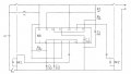
Here's my latest drawing.
Could not really make sense of your Mono ckt, grabbed a Pwr-Up one shot out of the cookbook. then used your 10 sec clock ckt.
Solved the VCC problem by utilizing a DPST K1
(Just put revised drawing on, don't need DPST K1, just SPST K1)
(OK added another drawing getting rid of curly cue)
Please analyze......
Attachments
-
 35.8 KB Views: 24
 -
 35.7 KB Views: 24
 -
 36.9 KB Views: 25
Last edited:
Nice drawings;now for a change ? If 60 sec Rt is is moved from P 4 to top of K 1 coil , Ct can discharge thru K 1 and be ready for a new cycle in about 30 sec. otherwise it must discharge thru 555 & leakage- time??
Period for second 555 approx. .35 R C ; Rt= [ 10+10 ]/.35X 50 = 1MΩ +-.
Period for second 555 approx. .35 R C ; Rt= [ 10+10 ]/.35X 50 = 1MΩ +-.
Bernard;
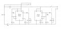
Having moved along before reading your last post, I have finally come up with the (almost) final design.
Attached are three pics showing the circuit we have been messing with using the two 555 timers.
I have also created/assembled the circuit using a 556, and, the third pic is the resulting waveform I get from it.
The math just didn't add up, spent all day substituting components till I got this close, etc....
I figure the initial long pulse is due to the capacitor first charging up, then things go as planned.
I appreciate your input, will get to work experimenting with your suggestions in the morning....
Perhaps you have some suggestion as to shortening the initial pulse?
Have a nice day
Oxbo
Attachments
-
 40 KB Views: 20
 -
 48.6 KB Views: 20
 -
 12.2 KB Views: 18


