
Hi,
Please help me understand the following...
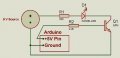
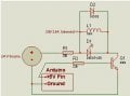
I have hooked up the following circuit:
1- 9V supply through an R to the cathod side of an LED.
2- The Anode side of the Led to pin 1(Collector) of a C547B Transistor.
3- Arduino Duemilanove Pin 13 to Pin 2(Base) of the sam Transistor.
4- the Ground of 9V source and the Ground of Arduino to Emitter of the Trans.
5- When the Arduino Pin 13 is Set to high, the LED Lights.
Questions:
A) Why is the Arduino pin sending just 1.15 V? Isn't it supposed to be 5V?
B) The Voltage at Tr. pins 1(collector) and 3(emitter) is 9V when the LED is off and 0 when lit, please explain the process... is it like with Base at 0V, the voltage is being held at the Tr. gates hence the 9V and when the Base is powered the gates open and the current flows to the LED and so the voltage at collector pin falls to Zero? That was a lot of making up I just did... whats the real story though?
thanks
Please help me understand the following...
I have hooked up the following circuit:
1- 9V supply through an R to the cathod side of an LED.
2- The Anode side of the Led to pin 1(Collector) of a C547B Transistor.
3- Arduino Duemilanove Pin 13 to Pin 2(Base) of the sam Transistor.
4- the Ground of 9V source and the Ground of Arduino to Emitter of the Trans.
5- When the Arduino Pin 13 is Set to high, the LED Lights.
Questions:
A) Why is the Arduino pin sending just 1.15 V? Isn't it supposed to be 5V?
B) The Voltage at Tr. pins 1(collector) and 3(emitter) is 9V when the LED is off and 0 when lit, please explain the process... is it like with Base at 0V, the voltage is being held at the Tr. gates hence the 9V and when the Base is powered the gates open and the current flows to the LED and so the voltage at collector pin falls to Zero? That was a lot of making up I just did... whats the real story though?
thanks

")


