amplifying ?

Thread Starter

Mathematics!

Joined Jul 21, 2008
1,036
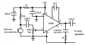
So I am trying to build a circuit that I can talk into the condensor mic and hear my voice out of the 8ohm 2 watt speaker.

I am using an audio amplifier chip LM386N 400mW

I have a 220 uf capacitor 15 volts connected from pin 1 to pin8

pin 2 is connected to ground
pin 3 is connected to mic + side
pin 4 is GND and is connected to ground
pin 7 is bypass and is not used at all
pin 6 is Vs which is connected to the + side of an 9 volt battery
pin 5 is output and is connected directly to one side of a capacitor ---then the one side of the speaker and the other side of speaker to ground.

I cann't hear anything.

So the only thing it could be is that I am not using a correct capacitor value infront of the speaker or I am not amplifing the current/voltage enough ?

8ohm 2 watt speaker => 1/2 amp current needed

When I measured the current between the speaker and the output pin taking the inbetween capacitor out I got approx 0.32 amps for the reading in current. (but maybe I measured wrong all try again tommarow and also measure voltage )

WTF is wrong or what am I over looking?
Thanks for any help.
And please don't refer me to a scheme digram for an intercom.
I know how to build everything from a scheme but I wanted to build it from the bare minium just using a few capacitors , and the chip. And I am more curious on why it is not working.

I am thinking I am not using the correct capacitor value in front of the speaker because I can hear the speaker siss sound a little but when I talk into it nothing changes.

Also I am still shakey on LM386 saying the output power is in the mW. It say's something like Vs=6V RL = 8 ohms
Pout= 125mW f = 1kHz Min = 250mW typical = 325 mW

But if my calculations was right then if I have current at .32 A then this means if the typical output power = 325mW
I would have to have a voltage = 325mW/.32A.

And from a 8 ohm 2 watt speaker => 1/2 A for current => Volts = 8ohms * 1/2A = 4 volts needed.

So I am assuming the voltage is the only problem and bumping that up to 4 while keeping the output current that I have would create around about 2 watts.

So then it should work then correct me if I am wrong in anything I said?
If so then it is just a question of creating a voltage tripler or something after the capacitor.

Thanks again and sorry for the long thread
 
Last edited:

SgtWookie

Joined Jul 17, 2007
22,230
If you want to keep it simple, use a dynamic microphone.

Otherwise, you're going to need a power supply and preamp for the condenser microphone.

Not what you wanted to hear, but that's just the way it is.
 

Audioguru

Joined Dec 20, 2007
11,248
Maybe you have an inexpensive electret microphone instead of an expensive condenser microphone that needs a 48V power supply?

You are missing the inportant 10 ohm resistor and 47nF capacitor in series at the output of the LM386 that are shown on every circuit in its datasheet.

You are also missing the important supply bypass capacitor.

You are also missing the resistor that powers the electret mic and the input coupling capacitor.

If the LM386 has a 6V supply then its output is typically only 325mW (0.325W) when it is clipping its head off with 10% distortion, or its power is only 200mW (0.2W) at clipping as shown on the graph in its datasheet, into 8 ohms.

Another graph shows how much power it dissipates as heat which is 200mW with an output of 200mW with a 6V supply and an 8 ohm load. Then its total power is 400mW from the 6V supply which is a current of 0.4W/6V= 67mA.

Make the circuit like this:
 

Attachments

Thread Starter

Mathematics!

Joined Jul 21, 2008
1,036
Ok , in your scheme above can the electric mic be substitued with the condenser mic element radioshack part 270-0090?

Also I am not fully understanding audio amplifier chip LM386N 400mW

If the LM386N chip can only produce 400mW of power at most. Then won't the output current and volatge always be pretty low?

I can see the case where if the output voltage = 1 volt and we had output power = 400mW = .400W this => a output current of .4 amps.

But either way if you are driving a 8ohm , 2watt speaker then you would need around current = 1/2 amp , and voltage = 4 volts. But how can a chip that is only rated to have at most 400mW of power output ever reach success in powering a speaker like this?

What are these chips meant to amplify ?
And I would think no matter what preamplifier circuit you created before the LM386 chip. It will be restricted to 400mW from the chip?
Is the total output power of the chip the actually power in + 400mW or is it just never more then 400mW out because no matter what preamp you build it would be restricted to 400mW which is **** for power out?
I am confused because I would think that using a larger battery source higher voltage and a higher cap to the gain would be the factor in how high the power out would be? And why would the power out be restricted to 400mW ?
The only thing you could do is use the LM386 to build a preamp circuit then build an amplifier circut from the output of the preamp LM386 400mW chip.

Thanks for clearing anything up with this one
Are these chips only to drive small power rated speakers and making preamp audio circuits? If so then I need a chip that has less restrictions then 400mW of output power?
 
Last edited:

Audioguru

Joined Dec 20, 2007
11,248
Ok , in your scheme above can the electric mic be substitued with the condenser mic element radioshack part 270-0090?
Radio Shack do not know anything about electronic parts.
It is not a condenser mic it is an electret mic like the one in my circuit.

If the LM386N chip can only produce 400mW of power at most. Then won't the output current and volatge always be pretty low?
Yes, like a cheap clock radio.

I can see the case where if the output voltage = 1 volt and we had output power = 400mW = .400W this => a output current of .4 amps.
If its output voltage is 1V RMS into 8 ohms then its output power is 0.125W.
Its RMS output current is 125mA.

But either way if you are driving a 8ohm , 2watt speaker then you would need around current = 1/2 amp , and voltage = 4 volts. But how can a chip that is only rated to have at most 400mW of power output ever reach success in powering a speaker like this?
If the voltage across the 8 ohm speaker is 4V RMS then its power is 2W. 4V RMS is 11.3V peak-to-peak. A 2W amplifier needs a supply voltage of about 15.3V and a max allowed output current of 706mA.
The LM386 has a max output at clipping of 450mW with a 9V supply.
With a 12V supply its max output at clipping is 528mW but the IC gets very hot.

What are these chips meant to amplify?
Low volume functions.

And I would think no matter what preamplifier circuit you created before the LM386 chip. It will be restricted to 400mW from the chip?
A preamp would simply make it more sensitive. its max output power remains the same.

Is the total output power of the chip the actually power in + 400mW or is it just never more then 400mW out because no matter what preamp you build it would be restricted to 400mW which is **** for power out?
Its max output current is limited. Its ability to dissipate heat is limited because it is small and cannot have a heatsink attached.

I am confused because I would think that using a larger battery source higher voltage and a higher cap to the gain would be the factor in how high the power out would be? And why would the power out be restricted to 400mW?
Look at its datasheet. It shows the output current is limited. It shows that it nearly melts (0.8W of heat) when its output is 528mW with a 12V supply.

The only thing you could do is use the LM386 to build a preamp circuit then build an amplifier circut from the output of the preamp LM386 400mW chip.
Use a low noise opamp to make a preamp. The LM386 is too noisy (hissss) to be a preamp.

I need a chip that has less restrictions then 400mW of output power?
Manufacturers make at least 70 amplifier ICs for car radios. One of them (TDA1562) doubles the supply voltage for power of 55W at low distortion into a 4 ohm speaker with a 14.4V supply.
A little (8 pins like the LM386) TDA2822M has an output power of 1W at low distortion into 8 ohms with a 6V supply because it has two amplifiers in a bridge like car radio amplifier ICs.
 

Thread Starter

Mathematics!

Joined Jul 21, 2008
1,036
Ok then my question is what makes the volume of the speaker louder?

It cann't be higher current because the LM386 doesn't really give out high current.

Is it the higher the voltage output by the LM386 because even this the chip cann't output to high of voltage restricted to it's power and heat disapation? (unless ofcourse the current was vary low)

I guess I don't have a frame of referance if your mic outputs current/voltage fluctations in the mAmps / mVolts then how much voltage/current would you need to hear it out an 8ohm 2watt speaker?
(i.e how much would you have to raise the mV and mA of the mic )

Would it just be like your above statement using V^2/R = P
so 2watts speaker = V^2/8 ohm => V = 4 volts so the current = 2/4 = 0.5 amps

So the current/voltage needed is 4 volts and 0.5 amps ?

Maybe these are the max ratings of the speaker? (Because if this where the case then the chip couldn't support it)
What is the exact ratings 8ohms 2 watts mean for a speaker?

And the most important question is how much does the current/voltage have to be to hear your voice out of the 8ohm 2watt speaker? The mic is at mV and mAmps really curious to know what voltage/current it needed interms of hearing audible sound?( <-- this is just a restatement of the above question feel free to answer interms of voltage, current , or power either one can be found from the others )

Thanks for any help with this

Me personally thought that the higher the current flowing thru the coils around the magnet of the speaker would induce a stronger pulling and pushing force which would mean more sound pressure occuring => louder sound.
Higher voltage to the some load "speaker" would imply higher current as well. So volume increasing would be directly proportional to current or voltage or power increaseing. But how much increase to hear sound?
 
Last edited:

SgtWookie

Joined Jul 17, 2007
22,230
Ok then my question is what makes the volume of the speaker louder?
More voltage across the speaker will make it louder. However, the amplifier has to be able to handle the power.

Your speaker has an impedance of 8 Ohms when fed a 1kHz sine wave.
E=sqrt(PR), so that's 4V RMS, or 5.66v peak to peak at 1kHz.

It can't be higher current because the LM386 doesn't really give out high current.
Yep, it's wimpy. No heat sinking.

Is it the higher the voltage output by the LM386 because even this the chip cann't output too high of voltage restricted to it's power and heat dissipation? (unless of course the current was very low)
It can't handle the power dissipation. If it's pushed too hard, the smoke will be let out of it. If pushed way too hard, you might even blow the lid off.

I guess I don't have a frame of referance if your mic outputs current/voltage fluctations in the mAmps / mVolts then how much voltage/current would you need to hear it out an 8ohm 2watt speaker?
(i.e how much would you have to raise the mV and mA of the mic )
It depends upon how good your hearing is. Humans have an extraordinarily wide range of hearing.

Would it just be like your above statement using V^2/R = P
so 2watts speaker = V^2/8 ohm => V = 4 volts so the current = 2/4 = 0.5 amps
Yep.

So the current/voltage needed is 4 volts and 0.5 amps ?
4v RMS on an AC sine wave.

Maybe these are the max ratings of the speaker? (Because if this where the case then the chip couldn't support it)
Yes.
What is the exact ratings 8ohms 2 watts mean for a speaker?
If you drive it harder than 4VAC RMS, you will break it. The voice coil will overheat and burn out.

And the most important question is how much does the current/voltage have to be to hear your voice out of the 8ohm 2watt speaker? The mic is at mV and mAmps really curious to know what voltage/current it needed interms of hearing audible sound?( <-- this is just a restatement of the above question feel free to answer interms of voltage, current , or power either one can be found from the others )
It depends on how good your hearing is. It really shouldn't take much, for persons with normal hearing. However, you have to actually give the amplifier something to work with other than noise. An electret mic with no preamp will result in just hiss being heard from the speaker.

You've asked basically the same thing three times in one post, so I'll just leave it at that for now.
 

Thread Starter

Mathematics!

Joined Jul 21, 2008
1,036
It depends on how good your hearing is. It really shouldn't take much, for persons with normal hearing. However, you have to actually give the amplifier something to work with other than noise. An electret mic with no preamp will result in just hiss being heard from the speaker.
Well I know the hearing range is between 20hz - 20kHz ( going on the save side but probably for older people less range )

But here is my main question now.
Plugging

pin 2 is connected to ground
pin 3 is connected to mic + side
pin 4 is GND and is connected to ground
pin 7 is bypass and is not used at all
pin 6 is Vs which is connected to the + side of an 9 volt battery
pin 5 is output to speaker

I measured 4 volts between one speaker node and the other side which is at the GND

Leaving out all capacitors.
This means the voltage is 4volts which if the current is enough should beable to drive sound out the speaker?
But I hear nothing when I tap the mic???

This say's to me that the capacitors are just used to create the ac wave in hz like if you want to have 1khz sinewave or 300 hz sinewave ,...etc
you have to rigg up the capacitor values correctly i.e use enough in parrell or series to make the correct sinewave cycles?

If this is true then why in your diagram do you need the capacitors/resistors etc on the left side of the LM386 chip?

I can see you needing the capacitors after the output of the LM386 to create the ac sinewave to drive the speaker. Since the speaker only works with ac I believe but correct me if I am wrong and it can work with pulsating dc?

So I guess other then the capacitor for the gain pin 1 and 8 and the capacitors/resistors for output of the LM386. What is the stuff for to the left of the chip other then the mic element for?????


Why do we need all the capacitors/resistors in your diagram ?

And if I make the output of the chip have a voltage of RMS 4 volts ac across the speakers at 1 khz
I should here sound correct me if I am wrong?
 
Last edited:

SgtWookie

Joined Jul 17, 2007
22,230
Well I know the hearing range is between 20hz - 20kHz ( going on the save side but probably for older people less range )

But here is my main question now.
Plugging

pin 2 is connected to ground
pin 3 is connected to mic + side
pin 4 is GND and is connected to ground
pin 7 is bypass and is not used at all
pin 6 is Vs which is connected to the + side of an 9 volt battery
pin 5 is output to speaker
Where is your schematic?

I measured 4 volts between one speaker node and the other side which is at the GND
Then your speaker has an open coil.

Refer to the Typical Applications in the datasheet. All of them have a capacitor between the output of the amplifier, and the speaker terminal. This is to block the DC current through the speaker, which will damage the amplifier and heat up the speaker voice coil.

Leaving out all capacitors.
That was not a good idea.
This means the voltage is 4volts which if the current is enough should beable to drive sound out the speaker?
You have a constant DC current flowing through the speaker voice coil.
But I hear nothing when I tap the mic???
Do you have the electret mic powered as in Audioguru's schematic?

If not, why not?

This say's to me that the capacitors are just used to create the ac wave in hz like if you want to have 1khz sinewave or 300 hz sinewave ,...etc
you have to rigg up the capacitor values correctly i.e use enough in parrell or series to make the correct sinewave cycles?
That really didn't make any sense.

If this is true then why in your diagram do you need the capacitors/resistors etc on the left side of the LM386 chip?
Capacitors block DC, but pass the effects of AC.

I can see you needing the capacitors after the output of the LM386 to create the ac sinewave to drive the speaker. Since the speaker only works with ac I believe but correct me if I am wrong and it can work with pulsating dc?
By keeping the voice coil constantly energized, you force the cone to it's limit of travel. This not only heats up the voice coil and amplifier, but also decreases the possible volume while increasing distortion.

Why do we need all the capacitors/resistors in your diagram?
Without them, it will not work properly.

And if I make the output of the chip have a voltage of RMS 4 volts ac across the speakers at 1 khz I should hear sound
correct me if I am wrong?
You may have burned out the speaker and/or the amplifier by this time, because you have not followed the typical applications recommendations.

You have abused both the amplifier and the speaker. I would not be surprised in the least if they are broken.
 

Thread Starter

Mathematics!

Joined Jul 21, 2008
1,036
Audioguru's schematic
Yes I am using Audioguru's schematic

But I just want to know what the capacitor from 2 to 6 pin is for?
And the 100uF and resistors 1k and 10k at the top left corner of his schematic is for??? Couldn't you have 9 volts go directly to 6 with no off shoot and couldn't you have pin 2 go directly to ground with no off shoot?
What is the benift of this add circuitary?

I know the capacitor 220nf by the mic and the resistor are shown in the diagram on the package of the condensor mic radioshack package but it say's it is optional?
Thanks for clearing up these questions

O and I have many 8ohm 2watt speakers lying around if I damage it as well as alot of LM386 chips and mics. Don't worry about this it is a learning process thanks for helping me.

Also can a speaker be used with pulsating dc or is it just meant to be used with ac? For instance if I add a diode to the output to create half hump postive sine waves (i.e pulsating 1khz dc would it be ok and hearable from the speakers)
 
Last edited:

SgtWookie

Joined Jul 17, 2007
22,230
Yes I am using Audioguru's schematic
OK, but you said you left out the capacitors. In that case, you were not following Audioguru's schematic, and you will not get good results.

But I just want to know what the capacitor from 2 to 6 pin is for?
The 470uF capacitor is to couple AC to ground. It's a bypass capacitor.
It was just the most convenient way to draw a capacitor across the amplifier's power supply pins.

And the 100uF and resistors 1k and 10k at the top left corner of his schematic is for???
The 1k and 10k resistors limit the current flow through the electret mic.
The 100uF capacitor connected from the junction of the 1k & 10k resistors to ground helps to eliminate any remaining noise on the power supply that the 470uF capacitor didn't get rid of. The mic must have a very stable power supply so that noise isn't amplified.

Couldn't you have 9 volts go directly to 6 with no off shoot and couldn't you have pin 2 go directly to ground with no off shoot?
What is the benefit of this add circuitry?
As Audioguru indicated, you need power for the mic, or it won't work.
He has given you a good plan on how to make it work.
If you don't follow his plan, it will either not work, or it will not work very well.

So, you can either follow his schematic and have a good chance of getting good results, or you can ignore his plan and enjoy the quiet hiss from your speaker.

I know the capacitor 220nf by the mic and the resistor are shown in the diagram on the package of the condensor mic radioshack package but it say's it is optional?
It really isn't optional. As I've already suggested, if you want good results, follow Audioguru's schematic.

O and I have many 8ohm 2watt speakers lying around if I damage it as well as alot of LM386 chips and mics. Don't worry about this it is a learning process thanks for helping me.
OK. Well, you might want to preserve as many of them as you can. You might need them.

Also can a speaker be used with pulsating dc or is it just meant to be used with ac? For instance if I add a diode to the output to create half hump postive sine waves (i.e pulsating 1khz dc would it be ok and hearable from the speakers)
You would get terrible distortion if you did that. The sound would be very unpleasant.

Speakers work best if they are operated using only AC. Any DC, or very low frequency AC, should be blocked or filtered out. Otherwise, you will have poor sound quality and overheating speaker voice coils.
 

Thread Starter

Mathematics!

Joined Jul 21, 2008
1,036
Thanks

The 470uF capacitor is to couple AC to ground. It's a bypass capacitor.
It was just the most convenient way to draw a capacitor across the amplifier's power supply pins.
I realize now you could have drawn the 100uF, 470uF on the right of the chip because they go directly from the 9volt supply to ground.

And I realize now the 10k resistor is to limit the current/voltage down so you don't exceed the max rating for the mic
( even know from doing the math why the value for the 10k resistor )

But why do you need the 1k between the 470uF and 10k resistor do you need 11k resistance for the mic or is their another purpose for the resistor draw between the capacitor? ( doing the math 10k would be enough to drop the voltage/current of a 9volt battery down to the mic's ratings. the extra 1k won't hurt though)

Also I would think that the 100uf and 470uf cap on the top left corner of the schematic would just always be fully charged since they are directly connected to the 9V unless some internal circuitary of the LM386 or speaker changes that in someway can't really see that though. Seems to me these things would just be fully charged all the time once the battey is connected? If they every discharged the path of least resistance would make it so no input to pin 2 was every made. Put another way pin 2 is always 0 volt 0 current.

The 470uF capacitor is to couple AC to ground

Thanks for any clarity on this

I don't really understand what the point of AC to ground coupleing does for us and why we used capacitance of 470uf for it? and have the 100uF their either? (maybe all this is just to steady the batteries 9volt dc voltage but if that was the case I could just use a regulator to do this )
 
Last edited:

SgtWookie

Joined Jul 17, 2007
22,230
And I realize now the 10k resistor is to limit the current/voltage down so you don't exceed the max rating for the mic
( even know from doing the math why the value for the 10k resistor )

But why do you need the 1k between the 470uF and 10k resistor do you need 11k resistance for the mic or is their another purpose for the resistor draw between the capacitor? ( doing the math 10k would be enough to drop the voltage/current of a 9volt battery down to the mic's ratings. the extra 1k won't hurt though)
A 9.1k and 1k in series would've been fine.

The point of the 1k resistor and then the 100uF cap is that any AC remaining on the 470uF cap will be "smoothed out" by the 100uF cap. The RC time of the 1k resistor vs the 100uF cap means that only very low frequency AC would make it through; and those low frequencies would be blocked by the 220nF cap.

It works both ways. Any signal generated by the electret mic won't be coupled back into the supply; it will be bypassed to ground by the 100uF cap.

Also I would think that the 100uf and 470uf cap on the top left corner of the schematic would just always be fully charged since they are directly connected to the 9V unless some internal circuitary of the LM386 or speaker changes that in someway can't really see that though. Seems to me these things would just be fully charged all the time once the battey is connected? If they every discharged the path of least resistance would make it so no input to pin 2 was every made. Put another way pin 2 is always 0 volt 0 current.
The battery leads have inductance and resistance. You need to have decoupling capacitors very close to the amplifier itself, and very close to the mic.

I don't really understand what the point of AC to ground coupling does for us and why we used capacitance of 470uf for it? and have the 100uF their either?
It's to get rid of the AC. You only want constant DC levels at those points.
 
Last edited:

Thread Starter

Mathematics!

Joined Jul 21, 2008
1,036
Ah , I got you but why choose the capacitance of 470uF , and 100uF
I mean I know the RC constant has to be enough to smooth out the fluctations. But their is alot of different chooses for your RC to = the same time if chosen different cap values and different resistor value?

Also for the capacitor from pin 1 to 8 which equals 10uf how do you know what value to use for this. Because pin 1 - 8 are for gain. Just how do you know by what capacitance you use how much your gain will be???
 
Last edited:

SgtWookie

Joined Jul 17, 2007
22,230
Ah , I got you but why choose the capacitance of 470uF , and 100uF
I mean I know the RC constant has to be enough to smooth out the fluctations. But their is alot of different choices for your RC to = the same time if chosen different cap values and different resistor value?
The idea is to get the RC time so high that any AC signal making it through the filter would not be audible; it would be too low in frequency. At the same time, you don't want to dampen the signal from the output of the mic to the input of the amplifier.

Also for the capacitor from pin 1 to 8 which equals 10uf how do you know what value to use for this. Because pin 1 - 8 are for gain. Just how do you know by what capacitance you use how much your gain will be???
It comes from the datasheet.

Go to National Semiconductor's website, and download the datasheet for the LM386.
Look at the top of page 3; the left column.
It explains exactly how to set the gain of the amplifier for anywhere from 20 to 200.
 

Audioguru

Joined Dec 20, 2007
11,248
I used a 470uf supply bypass capacitor because the schematic uses a little 9V battery and 470uf keeps its voltage from jumping up and down with the amplifier's current.
Most wall-wart power supplies have an internal capacitor then the 470uf capacitor can be reduced to 47uf.

A cheap clock radio has an output of up to 0.5W. The LM386 amplifier with a 9V supply has an output of 0.45W at clipping into an 8 ohm speaker.
 

Thread Starter

Mathematics!

Joined Jul 21, 2008
1,036
Ok , gotcha on the coupling capacitors and resistors.
And I got you on the gain capacitor I will look at the datasheet for this it is probably based on the internal circuitary of the LM386.

So the only other question until I completely understand this is
After the output of the LM386 why did you need choose 2 cap's and one resistor with those values?

Realistically since the cap's are hooked in parrell the total capacitance is 470.047uF the sum. Actually if you calculate the total impedance of the 2 cap's and 8 resistor you could use just one cap with one resistor or just one cap with the speakers resistor I would think?
But why did you choose these values ???
Curious on the output stuff aftter the output pin of the LM386 chip and before the speaker I know it's for creating the ac to the speakers but why those values. Is their a reason or can you use any capacitors for this? I don't think at this stage we are filtering anything so the RC time doesn't mean anything.


Also for the mic why do you need a 220nF cap after the output and 100k resistor? Why these values? If the 220nF cap is for creating an ac wave then why the value 220nF does it corospond to something with the hz of the ac wave or something? Or is this just another filter cap / resistor pair before sending input to the LM386? I would think the mic creates the ac voice waves and the cap/resistor don't need to be their if you don't care about noise or something?

Also for the 100k log resistor why that value and with the arrow does this mean you mean it to be a varible resistor?

Thanks for clearing up these last minute questions

Also I looked at the LM386 datasheet and if you don't connect the pins 1 and 2 it shows it will have the min gain of 20
But with the 10uF it will have the max gain of 200. It shows how to make a gain of 50 with a 1.2k resistor in series with a cap from pin 1 to pin 8. But I still don't have a formula for calculating the cap's / resistors needed for different values like gain of 66 , 78 , 150 ,...etc I would like to completely control the gain. Still not sure why 10uF cap give the max gain where did they calculated that from. Obviously for my application I will always want the highest gain but I am just curious of how to compute a random gain between 20 to 200 ...etc?

http://www.biltek.tubitak.gov.tr/gelisim/elektronik/dosyalar/6/LM386.pdf
 
Last edited:

SgtWookie

Joined Jul 17, 2007
22,230
So the only other question until I completely understand this is
After the output of the LM386 why did you need choose 2 cap's and one resistor with those values?
The single cap and resistor in series is a Boucherot cell.
Read here: http://en.wikipedia.org/wiki/Boucherot_cell


Also for the mic why do you need a 220nF cap after the output and 100k resistor? Why these values?
The 220nF cap will block DC and low frequency AC, but allow most audio frequencies to pass.

The 100k resistor is a potentiometer, it is a light load on the output of the mic, and allows controlling the level of input (as a volume control) to the amp.
 

Audioguru

Joined Dec 20, 2007
11,248
The value of a coupling capacitor is calculated from the lowest frequency you want and the load and source resistances for the capacitor.

For example, the 470uf output capacitor into an 8 ohm speaker will produce a response that is -3dB (0.707V) at 42.5Hz.
 

Attachments

Top