
 Facebook
 Google
 GitHub
 Linkedin
Hello, I am an aerospace engineering student, trying to get a better understanding in the field of electrical engineering.
I have a problem understanding how to choose the best topology for an amplifier.
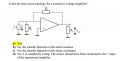
For example the question in problem1. It was asked if this topology is the best current-to-voltage amplifier. Although the right answer is marked yellow, I don't really care about the answer itself but more on how they got the answer.
As I see it now it would have picked answer c, because it seems that if I increase the value of Rs, more of the current will go trough R1 (knowing that the current into the amplifier = 0 and using Kirchoff's current law at the node above Rs). But it seems that this reasoning is wrong?
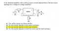
Also if I compare problem1 and problem2, the output type seems the same (Rl with a voltage across it). However in problem1 the transfer does not depend on the load resistance, but in problem2 it does.
Can anyone help me to understand how to pick the right topology or have a reference with a good explanation?
I have a problem understanding how to choose the best topology for an amplifier.
For example the question in problem1. It was asked if this topology is the best current-to-voltage amplifier. Although the right answer is marked yellow, I don't really care about the answer itself but more on how they got the answer.
As I see it now it would have picked answer c, because it seems that if I increase the value of Rs, more of the current will go trough R1 (knowing that the current into the amplifier = 0 and using Kirchoff's current law at the node above Rs). But it seems that this reasoning is wrong?
Also if I compare problem1 and problem2, the output type seems the same (Rl with a voltage across it). However in problem1 the transfer does not depend on the load resistance, but in problem2 it does.
Can anyone help me to understand how to pick the right topology or have a reference with a good explanation?
Attachments
-
 55.1 KB Views: 40
 -
 49.5 KB Views: 38

 .
. 






