
I just built a Class AB amplifier with a driver. I notice that a sawtooth wave is slightly bent as the ramp goes up. I think this is nonlinear distortion. I'd like to measure it, but I'm not sure how. I have a scope and a function generator. Can anyone tell me how I can measure the distortion and compare it to that which is considered acceptable for an audio amplifier?
Amplifier Measurement
- Thread starter PRS
- Start date
Scroll to continue with content
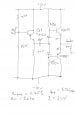
Here's the schematic. But all I'm really asking is how to measure the nonlinear distortion? And how does this amp compare with other class AB 2 Watt amps? Like I said, the distortion is only visible when the input voltage is high (> 9 Volts peak to peak). The amp is already built and in a cabinet. The parameters shown below are experimental.
Attachments
-
 45.9 KB Views: 47
Audioguru is right about negative feedback.
A transistor is a non linear device, thus its output does not vary linearly with the input. If you apply negative feedback the relationship between the input and output will be more linear.
Note that the gain of transistor (hfe) varies with Ic, Vcb, temperature and frequency.
A transistor is a non linear device, thus its output does not vary linearly with the input. If you apply negative feedback the relationship between the input and output will be more linear.
Note that the gain of transistor (hfe) varies with Ic, Vcb, temperature and frequency.
This amp has no voltage gain, that is absolutey right! Did I forget something? No. I built it as a result of failing to built a suitable feedback-based audio amp with discreet transistors. But rather than throwing in the hat, this compromise will allow me to use it as a lab instrument to work with several different types of voltage amplifiers and develop the finesse needed to make feedback-based amps. I simply punted; I did not quit the game.
But nobody has addressed the real issue: Given high Vp-p and a ramp signal, the rising edge of the ramp is bent slightly and therefore there is measurable nonlinear distortion. How is it measured and what are the stats so I can compare my 2 Watter with other 2 watters.?
But nobody has addressed the real issue: Given high Vp-p and a ramp signal, the rising edge of the ramp is bent slightly and therefore there is measurable nonlinear distortion. How is it measured and what are the stats so I can compare my 2 Watter with other 2 watters.?
David Bridgen
- Joined Feb 10, 2005
- 278
Your need to buy or borrow a distortion analyser and drive the amplifier with a sine wave.
However, the analyser will give you a figure for total distortion, it does not give separate figures for non-linear or cross-over.
However, the analyser will give you a figure for total distortion, it does not give separate figures for non-linear or cross-over.
Last edited:
There's got to be a way to correlate what I can measure on my scope. Take a ramp, for example. It has a nice long rising slope. If it's bent, and mine is, I can measure the end points and the midpoint and create a number representing the percentage of bend. That should be a figure of merit for an amplifier and I think it is.
Hi Paul,
Yes there are ways, but it will take quite a bit of space (and time) to explain.
One suggestion and some more questions.
What do square waves look like? What frequency are they? You need to look at both high and low to get the full picture.
Can you post a sketch of your ramps or square waves, because the way they 'droop' tells you a lot.
To measure (estimate) distortion on your scope you need a filter to remove the fundamental. What's left is distortion plus noise. Of course this technique only works with good sine waves as ramps etc are composed of lots of harmonically related components.
You can build a suitable notch filter quite simply for a single frequency. Are you prepared to do this?
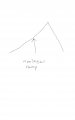
Here's a Paint drawing (I feel like a four year old with a crayon in my fist) of the ramp I spoke of. I wish I could take a photo so you could see it for yourself. Sorry about that.

As for the shapes of square waves I'm sure you know what they look like when they get distorted -- instead of sharp on and off times, they sag.
As for the notch filter the result would be the same as my seeing the sagging squarewaves and ramp -- a mental picture of undesired distortion. I'll stick with my memory of sagging waveforms, it's easier.
Thanks.
Attachments
-
 18 KB Views: 34
To calculate the distortion calculate the power the expected output signal would dissipate on a resistor and the power the actual output signal would dissipate on a resistor.
Then divide the actual power by the expected power.
Here is a link:
http://en.wikipedia.org/wiki/Total_harmonic_distortion
Then divide the actual power by the expected power.
Here is a link:
http://en.wikipedia.org/wiki/Total_harmonic_distortion
Paul, don't dismiss square wave testing so lightly.
Variation in the low frequency response affects only the horizontals, variation in the high frequency response only the verticals. No other waveform has this desireable property.
The Wiki (MIK) article only applies to true sine waves. The distortion calculation is not applicable to square or ramp waves.
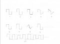
I have attached 10 sketches with explanations.
1) Poor (low) low frequency response, adequate high frequency response produces good verticals but horizontals are concave down.
2) Excessive low frequency response, adequate high frequency response produces good verticals but horizontals are concave up.
3) Poor power supply regulation / inadequate ripple filtering produces thickening of the horizontals
4) Adequate lowfrequency response, adequate high frequency response, but variable low frequency phase shift produces good verticals but horizontals that slope down.
5) Low, low frequency response, adequate high frequency response, but variable low frequency phase shift produces good verticals but horizontals that slope and sag down.
6) Adequate low frequency response, inadequate high frequency response with no phase shift, produces good horizontals and verticals, but all four corners are rounded. That is both horizontal to vertical transitions and vertical to horizontal transitions.
7) Adequate low frequency response, inadequate high frequency response with high frequency phase shift, produces good horizontals and verticals, but vertical to horizontal transitions only are rounded.
8) Adequate low frequency response, inadequate high frequency response, but low frequency phase shift curves all lines towards an approx triangle.
9) (Damped) oscillation at high frequency.
10) Inadequate hum filtering superimposed upon good output.
11) Not shown explicitly but low frequency oscillation looks like 10 with much more pronounced modulation, even to the extent of perhaps pulsing on and off.
Variation in the low frequency response affects only the horizontals, variation in the high frequency response only the verticals. No other waveform has this desireable property.
The Wiki (MIK) article only applies to true sine waves. The distortion calculation is not applicable to square or ramp waves.
I have attached 10 sketches with explanations.
1) Poor (low) low frequency response, adequate high frequency response produces good verticals but horizontals are concave down.
2) Excessive low frequency response, adequate high frequency response produces good verticals but horizontals are concave up.
3) Poor power supply regulation / inadequate ripple filtering produces thickening of the horizontals
4) Adequate lowfrequency response, adequate high frequency response, but variable low frequency phase shift produces good verticals but horizontals that slope down.
5) Low, low frequency response, adequate high frequency response, but variable low frequency phase shift produces good verticals but horizontals that slope and sag down.
6) Adequate low frequency response, inadequate high frequency response with no phase shift, produces good horizontals and verticals, but all four corners are rounded. That is both horizontal to vertical transitions and vertical to horizontal transitions.
7) Adequate low frequency response, inadequate high frequency response with high frequency phase shift, produces good horizontals and verticals, but vertical to horizontal transitions only are rounded.
8) Adequate low frequency response, inadequate high frequency response, but low frequency phase shift curves all lines towards an approx triangle.
9) (Damped) oscillation at high frequency.
10) Inadequate hum filtering superimposed upon good output.
11) Not shown explicitly but low frequency oscillation looks like 10 with much more pronounced modulation, even to the extent of perhaps pulsing on and off.
Attachments
-
 24.2 KB Views: 35
The square wave is a good test signal because (if you look at the Fourier expansion) it is made up of summing sine-waves starting at the square-wave frequency and extending upwards in frequency. So this is very much like doing a whole frequency sweep with one signal.
Triangle waves can also be used in a similar way, but the results are harder to interpret.
The original question:
[Soapbox]
I hear lots of people with their "music" turned up so much that either the amplifier clips (horrible distortion), or the speakers are overdriven, so it might just not matter that your amplifier is merely non-linear.
[/Soapbox]
For more precise measurements, you need the right equipment. Some scopes (like both my BitScope and my Fluke Scope) have modes where you can measure the distortion of a sine wave. Your amplifier would have very big numbers here (big is bad).
Having an amplifier with no voltage gain is totally reasonable, in that power is the product of voltage and current. This amplifier is designed for current gain. Hooked to a lower impedance speaker (lower than, say, earbuds), this can produce much more power. But hooked to the same output, there will be essentially no output power difference.
To be reasonable for amplifying music, you will have to tap the output and use it as negative feedback to a point on the left side of the circuit somewhere before the non-linear components (transistors) are used.
Triangle waves can also be used in a similar way, but the results are harder to interpret.
The original question:
The sort answer (as long as your input signal frequency is within a reasonable range) is if you can see the non-linearity, then it certainly can not be considered a quality amplifier. If you are just using it to drive a fire-alarm signal, then it is fine for that, but not for quality music....and compare it to that which is considered acceptable for an audio amplifier?
[Soapbox]
I hear lots of people with their "music" turned up so much that either the amplifier clips (horrible distortion), or the speakers are overdriven, so it might just not matter that your amplifier is merely non-linear.
[/Soapbox]
For more precise measurements, you need the right equipment. Some scopes (like both my BitScope and my Fluke Scope) have modes where you can measure the distortion of a sine wave. Your amplifier would have very big numbers here (big is bad).
Having an amplifier with no voltage gain is totally reasonable, in that power is the product of voltage and current. This amplifier is designed for current gain. Hooked to a lower impedance speaker (lower than, say, earbuds), this can produce much more power. But hooked to the same output, there will be essentially no output power difference.
To be reasonable for amplifying music, you will have to tap the output and use it as negative feedback to a point on the left side of the circuit somewhere before the non-linear components (transistors) are used.
The notch in the ramp is called "crossover distortion" and is caused because the output transistors operate in class-B instead of in class-AB.
Audio amplifiers use a transistor as an adjustable Vbe-amplifier instead of your two diodes. Then the idle current in the output transistors is adjusted for a smooth crossover transiston between the transistors.
Audio amplifiers use a transistor as an adjustable Vbe-amplifier instead of your two diodes. Then the idle current in the output transistors is adjusted for a smooth crossover transiston between the transistors.
Hey guys, these are some great comments. Mike, your article is well-taken. I want to compare what I make with those made by industry so that I know I'm up to standards. I'll be sure to test for THD using a sinewave. I'll do this when I get this amp off the shelf and hook it up to the voltage amp I'm working on now.
Studiot, your analysis of a square wave is a keeper. Mind if I file it? It makes for a great diagnosis chart. I've seen all of those shapes before. Some of them I'm very familiar with, others less so. Thanks for taking the time to draw those diagrams and post them with explanations. When I get a printer that page will go on my bulletin board.
Don, if I can see it's not linear, then it's an inferior amplifier? Okay. Fine things take time. And I know what you mean by people turning up their radios too loud. I've been experimenting with a voltage amp. More on that in a minute. As for equipment I'm lacking a power meter for uppity frequency and a spectrum analyzer. I haven't been able to spot one on EBAY yet, but I'll keep looking. All my equipment is lab quality, but old. I've got a Tec 475 scope that I feel is a Rolls Royce of 1975.
I realize my power amp is just that. I consider the voltage gain as a preamp. Right now I have on my bench an embrionic audio amp. It's made up of 4 op amps. It will have variable gain -- not just a volume knob but multipliers so that I can input various devices. Also bass and treble. Otherwise nothing fancy. I made the voltage gain part of it with a 6 position switch from x1 through x200. Now here's the part I was going to address above. You said if you can see it's distorted then it's no good. But here is a chart of gain verses 3dB point:
Gain -3dB
1 500 kHz
10 275 kHz
50 60 kHz
100 26 kHz
200 15 kHz
At these extremes (and with Vout=14volts) distortion exists -- sines are skewed, triangles rounded. But amplitudes and frequencies below these extremes -- at some point -- the output looks good. So I'm thinking most audio amps are like this. As long as I listen to the radio hooked up to this amp at a reasonable voltage level it will sound fine.
Audioguru and Don, I realize the need for feedback. I had determined not to use ICs and for this I had to use negative feedback. I'm familiar with the theory to some extent. But I got frustrated from many failures to get my own designs and the designs of others to work. I understand the need for active loads, etc. Again, I punted but I'm still in the game. With this power amp and separate voltage amp I have latitude to work it all out eventually at the bench.
Thanks, you all.")
Studiot, your analysis of a square wave is a keeper. Mind if I file it? It makes for a great diagnosis chart. I've seen all of those shapes before. Some of them I'm very familiar with, others less so. Thanks for taking the time to draw those diagrams and post them with explanations. When I get a printer that page will go on my bulletin board.
Don, if I can see it's not linear, then it's an inferior amplifier? Okay. Fine things take time. And I know what you mean by people turning up their radios too loud. I've been experimenting with a voltage amp. More on that in a minute. As for equipment I'm lacking a power meter for uppity frequency and a spectrum analyzer. I haven't been able to spot one on EBAY yet, but I'll keep looking. All my equipment is lab quality, but old. I've got a Tec 475 scope that I feel is a Rolls Royce of 1975.
I realize my power amp is just that. I consider the voltage gain as a preamp. Right now I have on my bench an embrionic audio amp. It's made up of 4 op amps. It will have variable gain -- not just a volume knob but multipliers so that I can input various devices. Also bass and treble. Otherwise nothing fancy. I made the voltage gain part of it with a 6 position switch from x1 through x200. Now here's the part I was going to address above. You said if you can see it's distorted then it's no good. But here is a chart of gain verses 3dB point:
Gain -3dB
1 500 kHz
10 275 kHz
50 60 kHz
100 26 kHz
200 15 kHz
At these extremes (and with Vout=14volts) distortion exists -- sines are skewed, triangles rounded. But amplitudes and frequencies below these extremes -- at some point -- the output looks good. So I'm thinking most audio amps are like this. As long as I listen to the radio hooked up to this amp at a reasonable voltage level it will sound fine.
Audioguru and Don, I realize the need for feedback. I had determined not to use ICs and for this I had to use negative feedback. I'm familiar with the theory to some extent. But I got frustrated from many failures to get my own designs and the designs of others to work. I understand the need for active loads, etc. Again, I punted but I'm still in the game. With this power amp and separate voltage amp I have latitude to work it all out eventually at the bench.
Thanks, you all.
Last edited:
I'll have to work it out again, but the problem with using diodes as bias is as they get near their back bias regions this shows as a non-linearity, and it will do this at the peaks of the wave form.
I have a similar problem with measuring distortion, though I don't know how to handle it. Back when I worked for Rockwell there was a HP instrument that measured percentage of distortion (which David mentioned already). The HP technique was that of a selective voltmeter, which filters out the base frequency and measures the left over signal.
The emitter resistors in that design are a form of feedback.
I made my standard mistake of missing the second page of posts before responding, so I repeated some of what has already been said.
Well spotted about the xover distortion, Guru.
Paul, please note that xover distortion is the exception, in more ways than one.
Because it operates at (or near) zero it cannot be cured by feedback. For the same reason its contribution to measures of averaged distortion is negligable.
However the ear is particulary sensitive to it.
Hopefully someone will draw better copy before including my sketches for wider distribution - but you are welcome to them, the information is common knowledge.
There is a school of thought which holds that a good amplifier should be linear and of low distortion in the absence of feedback. Feedback should be used to control, not to cure.
An amplifier with an open-loop distortion of 1% and an open-loop gain of 100,000 has a closed loop distortion of almost nothing when negative feedback reduces the gain to 20.
An LM3886 power amplifier IC has a typical harmonic distortion of only 0.002% at 1kHz, 58W into 8 ohms. Most of the "distortion" is inaudible hiss.
An LM3886 power amplifier IC has a typical harmonic distortion of only 0.002% at 1kHz, 58W into 8 ohms. Most of the "distortion" is inaudible hiss.
You May Also Like
-

A Q&A With Renowned Neuromorphic Chip Designer Chiara Bartolozzi
-

Using a Raspberry Pi Pico to Enhance a Vintage Radio Shack Microcomputer Kit
by Don Wilcher
-

Novosense Releases Higher-Performance Op Amps for Automotive
by Jake Hertz
-

Wi-Fi HaLow Flexes Its Wings, Extending Two Miles on Morse Micro SoC