AM modulator with MC1496 project problem

Thread Starter

tzitzikas

Joined Jun 3, 2007
41
Hello, i have done this project. It is an experimental oscillator - modulator for mw frequencies. The schematics are here:
oscillator:
http://tzitzikas.webs.com/oscillator-1.JPG
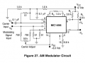
modulator:
http://tzitzikas.webs.com/modulator-1.jpg

The problem is that the designer told me to use an 1kohm variable series resistance between oscillator and modulator (after

c9=22n capacitor of oscillator) to adjust the carrier level. I saw that the 1kohm variable series resistance is not enought

because with 1kohm series resistance the audio was't very good. I think that the carrier level was high. So i change this

resistance with another 4.7kohm. Now i am using about 2kohm of this series resistance. The modulation is very good But i

think that the audio signal in the radio is not at the center of the frequency but a little above.
(The operation frequency is 1000khz but i listen the audio with quality and strong voice at 1003khz.)
which is the problem? how i can fix it, to listen the audio very well at center frequency and not at sideband?
 

retched

Joined Dec 5, 2009
5,207
Antenna length and proper shielding can make a difference in tuning and noise.

Have you tried using 2 1kOhm resistors to get 2K rather than jumping straight to th 4.7kOhm resistor?
 

Thread Starter

tzitzikas

Joined Jun 3, 2007
41
Antenna length and proper shielding can make a difference in tuning and noise.

Have you tried using 2 1kOhm resistors to get 2K rather than jumping straight to th 4.7kOhm resistor?
i don't use antenna but 50ohm dummy load. I am using 4.7ohm variable resistance to adjust the carrier at the point that i have the maximum output r.f signal with the best modulation in radio. Lower resistances of 2kohm increse the outpur r.f signal but the modulation in radio is not very good.
 

KL7AJ

Joined Nov 4, 2008
2,229
i don't use antenna but 50ohm dummy load. I am using 4.7ohm variable resistance to adjust the carrier at the point that i have the maximum output r.f signal with the best modulation in radio. Lower resistances of 2kohm increse the outpur r.f signal but the modulation in radio is not very good.

I would first do a test with an oscilloscope to see if it's really doing what it's supposed to. If you can HEAR distortion, you should be able to see it.

The 1496 is a fine IC; it was the core of the top end RACAL receivers, at the time the best H.F. receivers available at any cost.

Can you show us some oscilloscope shots of the modulated envelope? This would be a great help.

Also, check older ARRL Radio Amateur's Handbooks for A.M. transmitter alignment and testing.

Hope this helps.

Eric
 

stancomm

Joined Jun 21, 2010
5
Looking at the supplied schematics, I have a few questions;

1) Have you verified the carrier frequency and the accuracy of the receiver?
2) What is the bandwidth of the receiver you're using to listen to your signal?
2A) Does your test receiver have SSB capability? Try using that function and tune for natural sounding audio, then switch back to AM. That technique, assuming that the receiver is operating correctly, will set the receiver to exactly the center frequency of your transmitter.
3) Did you include R13 in the modulator schematic? You might try using that as the input to the modulator.
4) Is R2 properly connected along with the bypass caps? That network should provide a load for the input rheostat, "P2".

For wider control, "P2" could also be reconfigured as a potentiometer, feeding the RF into the top terminal, grounding the bottom terminal and connecting the wiper to the left hand end of "C7".

I suspect that this exercise is part of a learning experience for you? If so, has the course covered the relationship that the sidebands have to the carrier vs. the modulating frequency? If the bandwidth of your receiver is too narrow, less that 4 to 5KHz., you will run into behavior as you're describing.

Also, try using a simple "crystal radio" to listen with; a parallel LC network (tuned to 1MHz.) with a diode, one end connected to the LC's top end and a bypass capacitor and load resistor attached to the other (polarity of the diode here is unimportant), 10K and a .001 mic (1nFd.) should do. The bottom ends of the LC net, the bypass cap and load resistor are all tied to the ground of the input of your audio amplifier. You may need to connect the top of the LC net to the transmitter output through a small cap if you cannot hear anything through the audio amp, 10pFd. should be sufficient.
The bandwidth of that lash-up will be so wide that tuning will not be an issue... you'll hear everything that is there to hear in its proper relationship to the carrier.

I've used that same simple circuit, connected to a tape recorder to test the transmitted audio fidelity of AM Citizens Band radios. You cannot really tell what you sound like on the radio because you are also hearing your voice through the bony structure of your head... you really do sound different to other people around you than you do to yourself.

Good hunting...

Stan
 
Top