74hc04 chip in MultiSim?

Thread Starter

publicenemyobiwan

Joined Oct 24, 2010
3
Hello all,

This is my first post.

I currently have 2 issues.

1.) I am looking for a 74hc04 hex inverter chip on MultiSim (new to this as well) and I can only find a single inverter under that name that gives me a A/B/C/D/E/F option. Where can I find the actual hex chip on MultiSim?

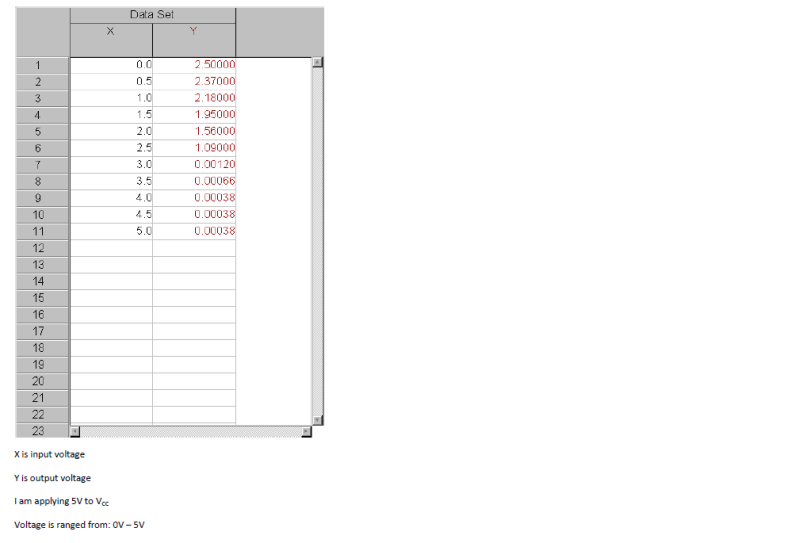
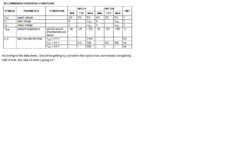
2.) I had given up on simulating the chip and went to test the inverter using actual components. When I applied chip power and varied the dc voltage to one of the inverters, I would expect Vcc at 0V and ≈ 0V when a high signal (5V in this case) is applied. The problem is, I'm getting ≈ half of Vcc when 0V is applied. :confused:
I have included a picture of what my circuit looks like built on ELVIS and I have also included data from what I have done so far.

ANY and ALL help is appreciated.

Thank you.

Obi.


thatoneguy

Joined Feb 19, 2009
6,359
The A-F are the 6 individual gates on the chip.

This is to prevent using the same gate twice, as well as allow you to find unused gates, in addition to MultiBoard so the PCB autorouting works.

When you choose the 74 series, choose different letters to denote which gate in a multi-gate chip you plan to use, they will all be specified as U1 if the same letters aren't chosen. Otherwise, MultiSim will think you want more than one IC even though only 2 gates are on the visible schematic.

For the prototype, ensure all inputs are tied to ground rather than left floating, you can use a 100k resistor to ground for input/used gates so that the voltage doesn't float. Also, add a 0.1uF cap between Pwr and Gnd close to the IC. Once it is set up like that, you should see the behavior expected.
 

Thread Starter

publicenemyobiwan

Joined Oct 24, 2010
3
Thanks for the response.

The deal is, how are you to apply a Vcc to the "chip" then? All I see are single gates. I need to have a Vcc supplied to the "chip" from MultiSim so I can read values obtained from the data sheet (bottom picture of the four). Without Vcc, all I see is the output square wave that I am applying.

Any ideas?
 

thatoneguy

Joined Feb 19, 2009
6,359
That is a kind of odd thing. All you need is a Vcc and GND somewhere on the same page, and it will assume you are hooking up to those.

Look in the samples folder for things to work with, or I can post a simple single 7404 Transistor testor/identifier I simulated with MultiSim.

It isn't intuitive, but it does make the entire circuit a bit more understandable and clear when viewing it.
 

Thread Starter

publicenemyobiwan

Joined Oct 24, 2010
3
If you could, that would be great. I'm still in the process of learning MultiSim and am kind of lost at the moment. All I see when I pull up the component list is a single inverter and not the chip set.

Sorry if this explanation is vague.
 

thatoneguy

Joined Feb 19, 2009
6,359
Brain fart. Had multisim on my notebook, which just came back from service, formatted and reloaded.

I'll need to dig through a drawer of thumb drives to find that one, or go through the reloading of multisim. I don't use it at home too often so forgot about it until just now.

Feel like a moron, since I have everything neatly backed up, EXCEPT that stupid notebook, so I'm trying to find all the OTHER stuff missing too now. <picture of me banging head against wall>
 
Top