555_Timer_Troubleshooting_Please

Thread Starter

motiv8d

Joined Aug 2, 2013
7
Hi. I have a Multi Wave Oscillator / Lakhovsky Coil powered by a tesla coil modulated by a 555 timer circuit. It is no longer working and I am trying to ascertain why and as such seeking the help of some 555 knowledgable people. The entire unit is about 4 years old, but no longer supported by manufacturer as they have a newer design.
I have replaced several components but the modulating circuit still does not seem to work properly. I am assuming that it should produce a squarewave output to terminals J2 and J3 that connect to an older type oil filled ignition coil.
Components replaced
Both transistors
All 3 Electrolytics
NE555 with a cmos 555 then an LM 555

When the unit is on now, the spark gap has no spark occuring, there seems to be no output from the emitters of either transistors, and J3 has it seems a constant 12V output (when I presume it should oscillate).

Testing done:
All resistors test at values
All diodes test with unlimited resistance one way

I have only a standard multimeter that does not have frequency, true rms or capacitance.

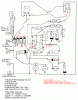
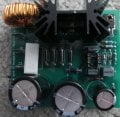
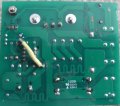
Attached is the circuit diagram as best as I can draw it (it is on dual sided circuit board), a photo of the top and bottom of the circuit and a picture of the entire unit to see how things fit together. (Except the square type ignition coil is not connected in the photo. Although the square type coil is connected in parallel with the oil filled ignition coil, there is no output connected - it is to hold the capacitance in line with tesla principles, which I do not fully understand)

Could someone please review the circuit and let me know what the output should be at various points so that I can test with my meter to determine where it is broken?

Also if anyone with knowledge of Tesla coil circuits could recommend any improvements in the modulating circuit, eg: potentiometer to control frequency or square wave timing, that would also be welcome.

Thanks kindly in advance

Motiv8d
 

Attachments

ian field

Joined Oct 27, 2012
6,536
D6 - D9 are probably zeners, you should check none of those are clamping at lower than rated voltage.

D4/5 and the resistors around them look like pulse width steering - I'd pay extra attention there as well.
 

Thread Starter

motiv8d

Joined Aug 2, 2013
7
Hi Ian
Thanks. These I have tested as follows:
Diodes, continuity one way only with resistance
Resistors tested that ohm rating was same as resistor specs.
Is it possible that these could test ok but then in operation be failing?
If so is there another way I can test these too?
All the best

Jesse
 

THE_RB

Joined Feb 11, 2008
5,438
There's definitely some nasty corrosion on your PCB. I would clean with with hot soapy water and a toothbrush, then brush with clean alcohol (metho etc) and a toothbrush, then brush with a clean grease to stop future corrosion (vaseline is fine).

The cause of failure with bad PCB corrosion is usually that contaminants and salts build up on the PCB and start to "leak" (partially conduct) which stops operation. Cleaning may be all that is needed.
 

Thread Starter

motiv8d

Joined Aug 2, 2013
7
Thanks The_RB
The picture of the circuit is actually an older one. Since then I have cleaned up the board as best as possible. I used vinegar and sodium bicarbonate - not sure if this is bad :confused: but came up a lot better. Since then I have replaced the aforementioned components and placed the jumper on the back of the board.

Here is a further update:
I have cleaned up the circuit diagram and added labels for a few unlabelled diodes as well and also fixed up part of the circuit diagram I had wrong around C4, D2, D3.
I also have taken voltages at all points with circuit on and put these onto a circuit diagram that might make it obvious to someone knowledgable as to where the problem is.
Both of these pictures are attached to this post.

Diode testing with Diode Check Setting on Multimeter resulted in:
Diode Forward Reverse
D1 0.602 1
D2 0.631 1.513
D3 0.598 1
D4 0.626 1
D5 0.623 1
D6 0.655 1
D7 0.655 1
D8 0.656 1
D9 0.656 1

Thanks
Jesse
 

Attachments

tracecom

Joined Apr 16, 2010
3,944
Apparently you have no continuity between pin 3 (2.19V) of the 555 and the 3.2k bias resistor (.01V) that goes to the base of T2, thus T2 cannot turn on. The track looks very bad on the top side of the board near the bias resistor; that could be where your break is.
 

THE_RB

Joined Feb 11, 2008
5,438
Yeah, the old photo shows the trans and maybe the resistors have issues.

It's definitely worth measuring the tracks with an ohmmeter (or multimeter's beepy test) as sometimes they can corrode through a track under the stop mask coating, it may not be easy to see by eye.
 

Thread Starter

motiv8d

Joined Aug 2, 2013
7
Thanks tracecom and RB

That track was definitely a problem, but unfortunately not the only one as the circuit has improved but is still not working correctly.
I have placed a jumper between 555 #3 (Output) and that 3.2k bias resistor and some voltages are now very different. A circuit diagram with updated voltages underlined is attached since this jumper.

I have also noted (due to a slip of the multimeter probe), that shorting pins 1 and 2 of Transistor 2 (Emitter and Collector respectively of the BD139 I think), that the spark gap makes a spark each time shorted. So is T2 broken or is the 555 part of the circuit not oscillating so as to cause the spark?

The voltages for that transistor are:
3 (Base?) - 11.75V
2 (Collector?) - 1.84V
1 (Emitter?) - 0.02V

For that transistor to work shouldnt the voltages need to be as follows?
BaseV < CollectorV and EmitterV < BaseV ?

If that is the case then either the Collector voltage needs to be higher or the base voltage needs to be lower. But my knowledge is only new and from reading some internet info on transistors.
So the other option would be that the new T2 is broken?

Unfortunately after taking those V readings, I mistakenly left the power on for about 30 mins. Both ignition coils became too hot to touch and shorting pins 1 and 2 on T2 no longer resulted in spark across spark gap. After letting it cool can now cause spark again manually.

I tested every circuit track I could ascertain with the meter and found a suspicious one between 555 pin 5 and C5 - I have resoldered this and it now seems good. It didnt change the operation or voltage readings across the board though.

Also pin 2/6 of the 555 seems to be a V that starts at close to 5V then over about a minute or so drops (faster initially, then slower) to 0.3V. Then sits around this reading. I do not understand what this 555 circuit 'should' do, so have no idea if this is correct or not.

As far as the 4 diodes connected in series, as I understand it the current should flow from the anode to the cathode, so that would be from the negative side of the electrolytics C1 and C2 and eventually to J2 and the collector of T1. Do I understand this correctly? If so then until the capacitors produce an output the the diodes shouldnt charge.

Another question I have is why is there 1.25V reading at T1 pin2 (collector?) ?

I am quite confused by this circuit so any help understanding what it 'should' be doing would be much appreciated thanks.

And I am not understanding why the C of T2 would be connected to the B of T1? And why the two Emitters would be connected together. Maybe I have the BCE incorrect on one or both of them? What I have and drawn the circuit as such is:
T1 BU931P NPN TO-247 Package --> 1,2,3 = B,C,E
T2 BD139 NPN --> 1,2,3 = E,C,B

And finally, what causes the corrosion in the first place? Before I removed it, between the 3.2K Resistor and the heatsink, there was about 2mm high of fluffy bluish corrosion with a powdery appearance.

Thanks again for any input.

Cheers
Jesse
 

Attachments

Thread Starter

motiv8d

Joined Aug 2, 2013
7
Oh also, when I short those two T2 pins (1 and 2), there is ouput V from C1 and C2. Correspondingly the V at D6/T1(2)/J2 jumps. I only have a standard DMM so for the instant of the capacitance discharge it is obviosuly not accurate, but the reading spikes afer the diode series is up over 100V.
 

Thread Starter

motiv8d

Joined Aug 2, 2013
7
Hey RB, just reading your page on DIY SMD microscope and noticed you are from Oz. I'm in West, where abouts are you?
 

THE_RB

Joined Feb 11, 2008
5,438
...
The voltages for that transistor are:
3 (Base?) - 11.75V
2 (Collector?) - 1.84V
1 (Emitter?) - 0.02V
...
For an NPN transistor, those DC voltages look like it has shuffled off its mortal coil (died). ;)

I would just replace the two transistors with new good ones. And the 555 timer IC. Those parts are cheap and easy to source. Then lift one leg of each diode free of the board, and test all diodes with your multimeter diode test.

It should all be fixable, but your best repair methodology is probably to clean/inspect and do a lot of replacing stuff rather than try to diagnose a fault based on voltage readings and such. :)

Re my location in Australia I'm in sunny Queensland where the weather is just starting to get nice and warm again. We just had a cold winter, some days as cold as 17'C I even went and put shoes on on some of the really cold winter days... ;)
 

Thread Starter

motiv8d

Joined Aug 2, 2013
7
Hi RB

Thanks, much nicer than Bunbury WA at the moment then
Would love some warm weather... :)

I have already replaced the 2 transistors and the 555.
Have to mail order as noone here carries them. I have a spare 555, but will order new transistors then now that the board (I think) is fully repaired.

The diodes I wouldnt even know what their specs are as there is no markings so hope ok once I pull of board and test.

The reason that I was asking about the correct function based on the specs as I was wondering about the small film caps that control the 555.

Cheers

Jesse
 

THE_RB

Joined Feb 11, 2008
5,438
Those caps are unlikely to be damaged. The most likely fault was that corrosion caused some errant conduction on the PCB which either turned the transistor(s) on full or at least caused a big heat increase in them.

It might also have leaked some high voltage through the semis, depending how high the voltages are on the PCB.

It's good that you replaced the more critical parts, and the diodes are easy to test you don't have to fully remove them, just lift one leg, and measure them, they are effectively "out of circuit" like that.

The diodes should measure about 0.6v or 0.7v on your meter's diode test, and in the other direction measure as open circuit.

Some resistors are worth testing like that also, especially lower value resistors that might normally have higher currents through them, ie <1k. Higher value resistors rarely blow from fault conditions like yours. :)
 

tracecom

Joined Apr 16, 2010
3,944
Depending upon how important this circuit is to you, perhaps you should consider rebuilding it on a piece of perfboard. You have already done the hardest part, which is reverse engineering a schematic. The hard to find components (e.g., coil) are reusable, and the others are fairly cheap.

Just a thought.
 
Top