555 Timer

Thread Starter

GRNDPNDR

Joined Mar 1, 2012
545
I just built this circuit following directions from one of our labs when I was in school, and now that it's assembled it will flash the LED, but the pot is useless.

I can even remove the pot from the circuit and it will still flash.

Where did I go wrong here??

I followed the directions instead of the schematic, but I just checked it and I'm fairly sure it's all wired right.

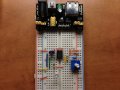
Here is a picture of my breadboard, and the lab I followed....which is a bit confusing at points I think.
 

Attachments

ericgibbs

Joined Jan 29, 2010
18,849
Also pin 2 and 6 and not linked and pin 4 is not connected.

EDIT:
Woops..See that pins 2 and 6 are linked across the top!
 

tracecom

Joined Apr 16, 2010
3,944
You have both sides of the VR connected to pins 6&2. In addition, pin 4 should be tied high, and although the schematic doesn't show it, there should be a .1uF cap from pin 1 to pin 8.
 

Thread Starter

GRNDPNDR

Joined Mar 1, 2012
545
Remove the blue jumper 25, on the left side of the chip, as it is shorting out the pot.
The instructions say to do this.... but I remember some of them weren't always correct, not sure if this was one of them.

Also pin 2 and 6 and not linked and pin 4 is not connected.

EDIT:
Woops..See that pins 2 and 6 are linked across the top!
Right, I missed the pin 4 connection, so I'll hook that to Vcc.

You have both sides of the VR connected to pins 6&2. In addition, pin 4 should be tied high, and although the schematic doesn't show it, there should be a .1uF cap from pin 1 to pin 8.
The VR?
 

Thread Starter

GRNDPNDR

Joined Mar 1, 2012
545
Got it working. Put power to pin 4, and removed the jumper on the pot....which I'm still confused as to why they said it should be there.

Also forgot about that handy power supply I bought a couple of weeks ago.
 

Attachments

ericgibbs

Joined Jan 29, 2010
18,849
Got it working. Put power to pin 4, and removed the jumper on the pot....which I'm still confused as to why they said it should be there.

Also forgot about that handy power supply I bought a couple of weeks ago.
hi,
It may appear to be working, but not in the way the design specifies.

That link across the pot is required, its in series with the 4k7 and the 10uF cap.

If the link is across the top two pins of the pot, the adjustment will be CW and if across the lower two pins the adjustment will CW.
 

Attachments

Last edited:

ericgibbs

Joined Jan 29, 2010
18,849
OK, so what is the difference?
The difference is that user may want to increase the 555 period as he turns the pot clockwise or have the option to decrease the period if he turns it clockwise.

I am making him aware of the pot sense options, nothing more than that.
 

nerdegutta

Joined Dec 15, 2009
2,684
The difference is that user may want to increase the 555 period as he turns the pot clockwise or have the option to decrease the period if he turns it clockwise.

I am making him aware of the pot sense options, nothing more than that.
OK, got a bit confused since both directions where clockwise. Thanks!
 

Thread Starter

GRNDPNDR

Joined Mar 1, 2012
545
If I connect that jumper across pins 1 and 2 of the pot, the light just flashes at maximum speed because it's bypassing the pot.

so I really don't understand the purpose of that jumper
 

ericgibbs

Joined Jan 29, 2010
18,849
If I connect that jumper across pins 1 and 2 of the pot, the light just flashes at maximum speed because it's bypassing the pot.

so I really don't understand the purpose of that jumper
If you look at my post #7 layout image, the 'extra' link has been removed.
 

Thread Starter

GRNDPNDR

Joined Mar 1, 2012
545
The problem is that you have both sides of the variable resistor connected to pins 6 and 2. (Seems like I already said that.)
Didn't know what you meant by 'VR' then forgot.

The schematic shows pin 2 and 6 connected to the pin 3 on the pot.

why would they have us build this circuit like this ?!?!?

If you look at my post #7 layout image, the 'extra' link has been removed.
I'll make those changes in a bit and see what happens.
 

Thread Starter

GRNDPNDR

Joined Mar 1, 2012
545
so I see now what I did, connecting pins 2 and 6 to the pot such as I did, but I didn't see the error until I looked at the two pics side by side.

not really sure why or how I did that....
 

Thread Starter

GRNDPNDR

Joined Mar 1, 2012
545
Yes, I powered it up at first and the chip got hot.....because I put the power supply in backwards.

But, it still works now that I've put the supply in correctly.


Pretty hearty devices these 555's

I've been trying to find a pre-made 555 timer that would plug into a breadboard like this little power supply/regulator but haven't found one yet. Well the one I did find, I didn't really like.
 
Top