555 timer

Thread Starter

GirishC

Joined Jan 23, 2009
58
Hi

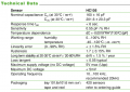
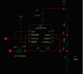
I am currently using LCM555 timer for generating variable frequency based on relative Humidity (RH) of surrounding. The LCM555 is configured as astable multivibrator and centered at 20KHz. RA = 24K, RB = 200K and C is capacitive sensor having value of 160pF at 30C, 0%RH. The C is given by formula

C = C0*[1 + HC0*RH]

C0 = 160pF at 30C, 30%
HC0 = 3420ppm/%C
RH = % relative humidity

temperature derating factor is
dC= - 0.0019*(T-30) pF
T = temperature in C

When I sweep the RH from 0% to somewhere 45% my 555 timer stops working. I have to replace the LCM555 timer and keep RH below 45%. I have similar circuit with RA = 40.2K, RB = 360K and C is 105pF and centered at frequency 18KHz and it works very fine till 98%.

When I talk to National about this problem, I received a feedback saying I can not use this chip beyond 5.6KHz (max), according to datasheet. I have queries based on my experiment

1. How can upper limit being 5.6KHz is possible. We have many application where 555 used goes much above 100KHz.
2. What causes failure of LCM555 and why it works in other configuration? I have verified the current requirement of discharge pin and trigger pin. What am I missing?
3. What is the solution to my problem.

Could anyone through light on this?

Girish
 

bertus

Joined Apr 5, 2008
22,276
Hello,

Do you have the datasheet of the RH sensor ?
Does it function from 0 to 100 % or is there a limitation ?

Greetings,
Bertus
 

Thread Starter

GirishC

Joined Jan 23, 2009
58
Hello,

Do you have the datasheet of the RH sensor ?
Does it function from 0 to 100 % or is there a limitation ?

Greetings,
Bertus
Hello

Yes, I do have datasheet for the sensor. You can google it for HC105 and you will get it. Yes the sensor do work from 0% to 100% RH. As such there is no limitation mentioned on the datasheet.
 

bertus

Joined Apr 5, 2008
22,276
Hello,

I found the data sheet. The limitation is above 60 °C.
In the datasheet is said the optimum working frequency is 20 khz.
Can you post a schematic of the 555 circuits you made ?

Here is also an other idea from EDN for an oscillator with a humidity sensor :


Greetings,
Bertus
 

Attachments

SgtWookie

Joined Jul 17, 2007
22,230
Hi

I am currently using LCM555 timer...
Did you mean LMC555 timer?
... for generating variable frequency based on relative Humidity (RH) of surrounding. The LCM555 is configured as astable multivibrator...
Please post your schematics. Use the "Go Advanced" button, then "Manage Attachments". .png format files are preferred. .jpg images are too lossy.
...and centered at 20KHz. RA = 24K, RB = 200K and C is capacitive sensor having value of 160pF at 30C, 0%RH. The C is given by formula

C = C0*[1 + HC0*RH]

C0 = 160pF at 30C, 30%
HC0 = 3420ppm/%C
RH = % relative humidity

temperature derating factor is
dC= - 0.0019*(T-30) pF
T = temperature in C

When I sweep the RH from 0% to somewhere 45% my 555 timer stops working.
I have a feeling that you're using pin 7, with a low-value resistor to Vdd. Excess current will burn up the timer.
I have to replace the LCM555 timer and keep RH below 45%. I have similar circuit with RA = 40.2K, RB = 360K and C is 105pF and centered at frequency 18KHz and it works very fine till 98%.

When I talk to National about this problem, I received a feedback saying I can not use this chip beyond 5.6KHz (max), according to datasheet.
If it's an LMC555, this is incorrect. It can approach 3MHz.
I have queries based on my experiment

1. How can upper limit being 5.6KHz is possible. We have many application where 555 used goes much above 100KHz.
5.6kHz is quite do-able. 5.6MHz is out of the question.
2. What causes failure of LCM555 and why it works in other configuration? I have verified the current requirement of discharge pin and trigger pin. What am I missing?
You need to post schematics of your circuit(s), exactly as they are built.
 

Thread Starter

GirishC

Joined Jan 23, 2009
58
Hello,

I found the data sheet. The limitation is above 60 °C.
In the datasheet is said the optimum workingfrequency is 20 khz.
Can you post a schematic of the 555 circuits you made ?

Here is also an other idea from EDN for an oscillator with a humidity sensor :


Greetings,
Bertus
You are right, above 60C I can not take RH to 100%. But you know what, it fails at 45%, 30C. Thanks for the circuit idea. Here is the circuit

It seems I am unable to upload the schematic...but for your refernce its a normal astable with 24K and 200K resistors.

Girish


Thread Starter

GirishC

Joined Jan 23, 2009
58
Did you mean LMC555 timer?

Please post your schematics. Use the "Go Advanced" button, then "Manage Attachments". .png format files are preferred. .jpg images are too lossy.

I have a feeling that you're using pin 7, with a low-value resistor to Vdd. Excess current will burn up the timer.
If it's an LMC555, this is incorrect. It can approach 3MHz.
5.6kHz is quite do-able. 5.6MHz is out of the question.
You need to post schematics of your circuit(s), exactly as they are built.
Here is the schematic...
 

Attachments

Thread Starter

GirishC

Joined Jan 23, 2009
58
Hello,

I found the data sheet. The limitation is above 60 °C.
In the datasheet is said the optimum working frequency is 20 khz.
Can you post a schematic of the 555 circuits you made ?

Here is also an other idea from EDN for an oscillator with a humidity sensor :

Here is the schematic...

Girish
 

bertus

Joined Apr 5, 2008
22,276
Hello,

I think that the sensor has to be used in a resonant circuit without DC on it.
This could be an oscillator with a LC part with the sensor as the C.

Greetings,
Bertus
 

Thread Starter

GirishC

Joined Jan 23, 2009
58
Did you mean LMC555 timer?

Please post your schematics. Use the "Go Advanced" button, then "Manage Attachments". .png format files are preferred. .jpg images are too lossy.

I have a feeling that you're using pin 7, with a low-value resistor to Vdd. Excess current will burn up the timer.
If it's an LMC555, this is incorrect. It can approach 3MHz.
5.6kHz is quite do-able. 5.6MHz is out of the question.
You need to post schematics of your circuit(s), exactly as they are built.
You are right, its LMC555
 

Thread Starter

GirishC

Joined Jan 23, 2009
58
Hello,

I think that the sensor has to be used in a resonant circuit without DC on it.
This could be an oscillator with a LC part with the sensor as the C.

Greetings,
Bertus
This sounds interesting...something different...I will have to give try for it...Its a huge change for me!
 
Top