Facebook
 Google
 GitHub
 Linkedin
Received a request by a new member "Jure George" requesting help with a modification to a circuit I posted. I have been talking to him via email, but wanted to make the circuit idea public here so that I don't go and cause him to buy parts he doesn't need, or to design a circuit that won't work. Here is the info for all to contemplate and aid in designing...
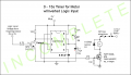
See Circuit diagram below.
Jure George said:Hi, I would like to know if you would be able to modify the Circuit you have posted for the 10 sec. Timer using a 555 and a push button trigger with a relay in the Circuit.
I would like a Circuit with the same Variable operating time of 0 Sec. to approx. 15 Sec. Triggered by a small level signal, 5v. No relay needed But circuit must be able to drive small motor 1-2 A. Main battery Supply 6v - 12v max.
Could you please send me the circuit plan ?
Thanks,
iONic said:Sorry to reply so late...
Let me get this straight:
You want the 555 timer to be triggered by a 5V logic signal. Will it be momentary, +5V, or -5V or do I have a choice?
Below is start, but may need some rewiring for the trigger. As it stands now, a momentary push brings Pin 2 of the 555 to 0V and thus starts the timer. The Motor you are driving, is it AC or DC?
Jure George said:Hi iONic
First Thanks for replying to my question. The circuit I need would be triggered by a Positive 5v and the Motor would be D.C. OR whatever else could be used. So If I have listed all my needs below please let me know:
- 555 I.C
- Main D.C Battery Supply 6v - 12v max. ( Common Battery values used 6v, 7.2v,7.4v,12v )
- To Drive a D.C motor, max. 1-2A
- Variable Opperational time ( Time it Runs ) 1 Sec. Motor On - 15 Sec. Running
- Positive 5v Signal used to trigger the start of the 555 Timer Circuit
- Fused to protect Circuit from D.C Motor failure
I think I have given you all my specs I need. Please let me know if you can modify the Circuit to work with these Specs. All this for a Circuit to be used in Remote Control Boats / Ships and Submarines ? The Smaller the physical size of the circuit, the more likely it will fit in a r.c submarine and small r.c boat.
Look forward to seeing your circuit.
Thanks,
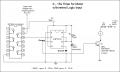
See Circuit diagram below.
Attachments
-
 27.9 KB Views: 127
")