555 Timer Based Synth/Piano

Thread Starter

ClimateController

Joined Dec 23, 2012
19
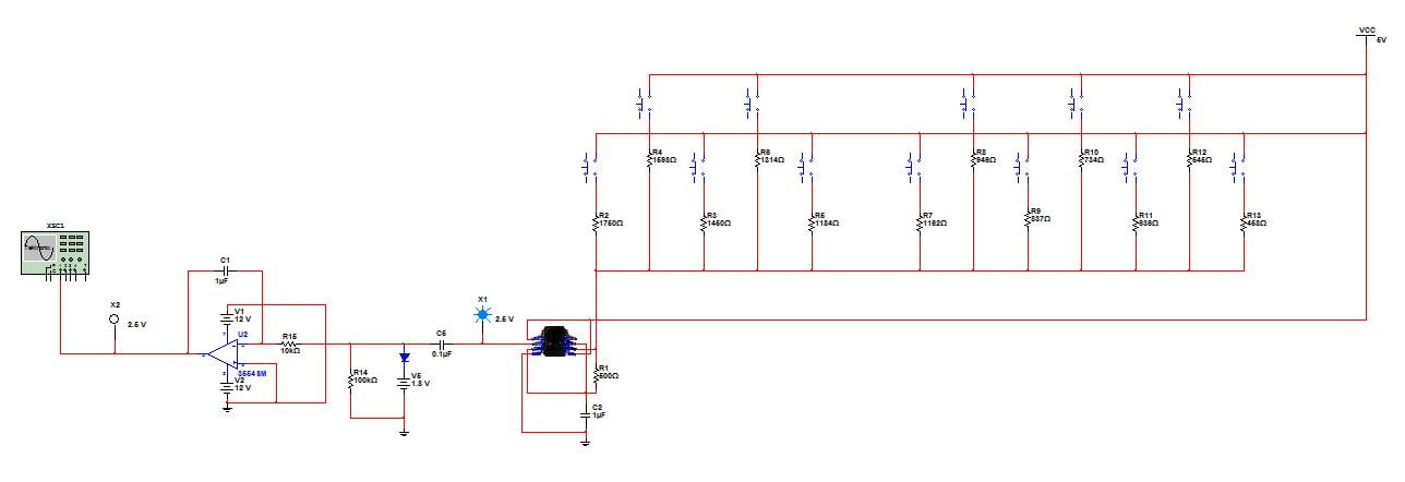
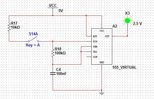
I am making a 555 timer based synth as my Integrated Circuits term project. It is polyphonic and spans one octave. It is a pretty simple design so I decided to make things interesting - keep the professor interested - by trying to use op amp integrators to turn the 555 output into sine waves. I soon realized, however, that op amp integrators require bipolar inputs for them to properly do the required conversion i.e. square to ramp to sine. I could use capacitor reset circuitry to hopefully eliminate this problem but this was a real blow to my confidence. Can you please tell me how I can make my synth more impressive? I am looking for suggestions that are simple to implement. Thank you in advance for your help. :)
 

THE_RB

Joined Feb 11, 2008
5,438
You can get a "sinewave" from a 555 fairly easily but it won't be a perfect sine.

An old trick I have used it to take the "output" from pin 6 (the oscillator cap). This is a cap charge waveform that goes between 1/3 Vcc to 2/3Vcc in amplitude, and is roughly triangular in shape with some curves.

It is easy enough to add a single RC filter (one resistor, one cap) to that waveform to make it into a good enough "sine" for music instrument use. You need to make the resistor reasonably high in value so it does not affect the oscillator frequency that much, but if you are going for a polyphonic project (one 555 per note) then that shouldn't be a problem.
 

Thread Starter

ClimateController

Joined Dec 23, 2012
19
Thanks. Yes, I am going to use RC filters to achieve sine waves but I have noticed the gain suffers as a result. Should I use an op amp based amplifier? Can I use any resistor combination to achieve the desired gain or are there power considerations associated with for example a gain of 10 achieved using a 10 k ohms and 1 k ohms resistor combination (inverting amplifier)?
 

THE_RB

Joined Feb 11, 2008
5,438
Thanks. Yes, I am going to use RC filters to achieve sine waves but I have noticed the gain suffers as a result. Should I use an op amp based amplifier? Can I use any resistor combination to achieve the desired gain or are there power considerations associated with for example a gain of 10 achieved using a 10 k ohms and 1 k ohms resistor combination (inverting amplifier)?
If the 555 runs on say 9v, the waveform on pin 6 will be 3v peak to peak. An RC filter tuned for the "note" won't reduce it too much, maybe to 2v peak to peak on the sinewave signal.

That is still a strong enough signal to go to any guitar amp or instrument amp, or even into the RCA inputs on most HiFi amps.

But by all means if you want a larger signal out, or need to add gain to compensate for resistor mixing of lots of notes, then just add one opamp with a smallish gain (like the gain of 10 you suggested) AFTER resistor mixing all the notes with high value resistors.
 

Thread Starter

ClimateController

Joined Dec 23, 2012
19
Thanks for being so helpful. :) Anyway, since we are working on a tight schedule, I won't be making a polyphonic synth. I am gonna use a clamper to shift the 555 output down and use an integrator to change the wave shape. I have got it to work but the 555 timer is being troublesome. Its output is high even when it should be low as you can see in the attached screencap. This totally defeats the purpose of the clamper. I am sure it is only a problem with the software I am using (Multisim) but I would still like your input as to what could cause this.


THE_RB

Joined Feb 11, 2008
5,438
I can't see a "screen capture" only the schematic. Also, the schematic is not great and leaves us guessing the pin numbers on the 555 and guessing which wires join and which jump over other wires?

Also I have no idea why you need the "clamper"? If you are AC coupling the signal that comes out of the 555 then all you need is a resistor(s) to set the final DC average voltage (and amplitude).
 

Thread Starter

ClimateController

Joined Dec 23, 2012
19
This is what I mean. The 555 timer output is high even though the switch is closed. I am confident it has something to do with Multisim because this exact circuit has worked perfectly in other instances. Have a look:


THE_RB

Joined Feb 11, 2008
5,438
Ahh I see now your circuit is not taking the output from pin6 (as I said earlier this gives a much more "sine" shaped initial signal).

Take the output from pin6, and run it through a capacitor (AC coupled) which will couple the AC signal but not reproduce the DC "hi" voltage coming from the stalled 555 timer.

If you want the stall voltage to be low (or 0v for audio use) just AC couple the signal through a cap and use a high value resistor (270k? 330k?) from the output of that cap to ground.

Total setup;
1. output from pin6
2. RC lowpass filter (through resistor, then cap to ground)
3. through a cap (AC coupled) to 330k resistor to ground
4. (output is from the 330k resistor).
 

Thread Starter

ClimateController

Joined Dec 23, 2012
19
I have realized using a clamper and two integrators isn't exactly the best way to convert the 555 output into sine waves. Can I use an active bandpass filter instead? I used a 4 pole bandpass filter (Bessel) to see how the circuit would respond and it does the job. As far as the gain is concerned, there is only a variation of 0.43 V from 518 Hz to 955 Hz. But when I look at the frequency response, it looks very weird. These are the values I used:


THE_RB

Joined Feb 11, 2008
5,438
Why bother with so many parts? You will have to duplicate that for every single "note" oscillator!

NOBODY will ever notice a difference between a 90% good sine "note" from pin6 through one RC (one resistor, one cap) and a 99% good sine "note" from a complex filter circuit.
 

Thread Starter

ClimateController

Joined Dec 23, 2012
19
I am actually making a monophonic piano now. Polyphonic is too much work. This is why I am hoping I can use a bandpass filter to filter frequencies from 500 to 950 Hz.
 

THE_RB

Joined Feb 11, 2008
5,438
Sorry my mistake, I thought you said you were only going monophonic now as an intermediate stage.

A bandpass filter is more complex as it tries to eliminate frequencies both too high, AND too low.

Just use a low pass filter. The 555 waveform won't contain frequencies lower than the fundamental, only higher frequencies. :)
 

Thread Starter

ClimateController

Joined Dec 23, 2012
19
Can somebody tell me how I can add the signals from two separate 555 timers and feed them to a speaker? Basically, how do I connect two 555 timers in series?
 
Just add a opamp buffer to each "oscillator", then sum them with resistors, if your looking at outputting multiple tones through the same output.

IE an analog mixer.
 
Top