http://www.allaboutcircuits.com/vol_6/chpt_6/8.html
The above is concerning these five questions.
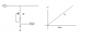
#1How do you calculate the frequency for the above circuit at the above E-book site?
#2, what is the difference between sawtooth wave and ramp wave?
#3 The Television begins at the left and move to right but the oscilloscope don't assume,Why ?
#4 In regard to the television pixels,do they enter thru the cathode of CRT?
#5 Is the Scanning,that is,Horizontal and vertical plates on the CRT tube automatic or fixed procedure that always happen when a signal is not there?, gray scale,not color.
The above is concerning these five questions.
#1How do you calculate the frequency for the above circuit at the above E-book site?
#2, what is the difference between sawtooth wave and ramp wave?
#3 The Television begins at the left and move to right but the oscilloscope don't assume,Why ?
#4 In regard to the television pixels,do they enter thru the cathode of CRT?
#5 Is the Scanning,that is,Horizontal and vertical plates on the CRT tube automatic or fixed procedure that always happen when a signal is not there?, gray scale,not color.
Last edited by a moderator: