I thought it best to start a new thread with a different design.
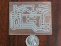
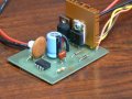
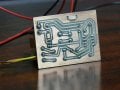
I changed designs to use a mosfet style transistor I found a nice one here The schematic is below. I could not find the BUZ11 mosfet or the schottky diode locally so I made some substitutions. It all works good , I would just like someone to look over my shoulder to see if I did anything really bad.
I first assembled it on the bread board with the only changes being an IRF510 mosfet and a 1N5400 diode. It ran my motor , but the 50K pot only ran the motor between about 75-100% . So I started playing with R1 the pot and C1. What I ended up with is in the schematic below. With the 10K pot I now have about 95% of usable adjustment. The motor starts at 2.2 Volts and I have a max of about 10.3 volts ( Out of 12.1 V ) With this circuit the motor is drawing 2.3amps no load and about 3 loaded up. I did put a heatsink on the mosfet.
Unless I did something really stupid I think I will go with this design.
Original design is on top and the modified design is below.
Attachments
-
 75.7 KB Views: 410