555 monostable resetting before timing out

Thread Starter

dsdrewyoe

Joined Apr 7, 2013
9
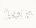
I have a 555 timer set up in monostable mode (9 seconds) triggered by a magnetic reed switch connected to pin 2 and grnd to control a relay and light. The output from the chip (pin 3) drives a TIP3055 NPN Darlington pair for current carrying purposes. It is run off of a 20amp 14v power supply and uses a 12v regulator chip. Pin 4 is set high and pin 5 is floating. The timer works great, but when another device connected to the power supply switches on, the 555 circuit resets and pin 3 goes low. The circuit voltage never drops below 12V. I think it is seeing it as a pulse to reset somehow. Any ides on how to correct this? I have read that the power side and ground should be tied together by a decoupling or bypass capacitor Could that be my issue? Thanks in advance

Dave
 
Last edited:

Thread Starter

dsdrewyoe

Joined Apr 7, 2013
9
praondevou - pin 2 is tied to Vcc with two resistors in series and one side of the switch is connected in the middle. I had read that this keeps switch bounce to a minumum. I am not sure on the values. I can check tonight and post back. What would you recommend?

tracecom - my pin 5 is just open and I'm also missing the .1uf from pin 1 to pin 8. I will get the caps and put them in the circuit. Are these just ceramic caps and is their purpose to keep noise out of the system? I found this on the TI spec sheet - Is this what we are doing?

ADDITIONAL INFORMATION

Adequate power supply bypassing is necessary to protect associated circuitry. Minimum recommended is 0.1
μF in parallel with 1μF electrolytic.

To both of you - thanks for the help. I'm familiar enough to get myself into trouble with a circuit when something weird happens, and you guys are helping me get out :)
 
Last edited:

tracecom

Joined Apr 16, 2010
3,944
tracecom - my pin 5 is just open and I'm also missing the .1uf from pin 1 to pin 8. I will get the caps and put them in the circuit. Are these just ceramic caps and is their purpose to keep noise out of the system? I found this on the TI spec sheet - Is this what we are doing?

ADDITIONAL INFORMATION


Adequate power supply bypassing is necessary to protect associated circuitry. Minimum recommended is 0.1
μF in parallel with 1μF electrolytic.
Yes, just ordinary ceramic caps. The .01μF on pin 5 is listed as optional on the 555 datasheet, but is recommended. It helps to prevent electrical noise from affecting the control pin, and I always use it. It's cheaper to put in, than to take a chance on erratic operation.

A .1μF is always a good idea on the power pins of any IC; it never hurts and often is required for noise protection. Depending on the power supply you are using, an electrolytic can also help; it can be as small as 1μF or as large as you want. The 555 itself can cause noise on the power line and so often is the cause of resets.
 

Thread Starter

dsdrewyoe

Joined Apr 7, 2013
9
I had my kid look at my supplies at home and I have a 22uf electrolytic and a .1uf ceramic for the power supply. I have a .01uf that is a metal film or polyester film cap for the pin 5 connection. From what I read this should work. Am I correct on usage? I will put them in the circuit and let you know how I fare. Thanks for the help.

Dave
 

tracecom

Joined Apr 16, 2010
3,944
I had my kid look at my supplies at home and I have a 22uf electrolytic and a .1uf ceramic for the power supply. I have a .01uf that is a metal film or polyester film cap for the pin 5 connection. From what I read this should work. Am I correct on usage? I will put them in the circuit and let you know how I fare. Thanks for the help.

Dave
Should be fine.
 

Thread Starter

dsdrewyoe

Joined Apr 7, 2013
9
SUCCESS!!!!

I set up the caps like you advised and it worked perfect. I can switch on multiple items and the 555 stays latched for the 9 seconds just like it should. Since I did both at once (pin 5 and the power supply decoupling), which do you think it was? I am not real concerned as it works and will always include both in my 555 circuits in the future. Just curious

Thanks to both of you for the advice.


Dave
 

tracecom

Joined Apr 16, 2010
3,944
SUCCESS!!!!

I set up the caps like you advised and it worked perfect. I can switch on multiple items and the 555 stays latched for the 9 seconds just like it should. Since I did both at once (pin 5 and the power supply decoupling), which do you think it was? I am not real concerned as it works and will always include both in my 555 circuits in the future. Just curious

Thanks to both of you for the advice.


Dave
Congratulations, and you are welcome. In my opinion, the cap from pin 1 to pin 8 is the most important, but at 15 cents or less each, I put them both in. :)
 

Thread Starter

dsdrewyoe

Joined Apr 7, 2013
9
Bummer - circuit not 100%:( Getting there though...


Being the excited guy, I went out and played with the circuit this morning. I had it reset prematurely once or twice out of maybe 15 tries (prior it reset 100% of the time). So I assume we are still getting something coming through the power to make it trip. I have the 22μf electrolytic and .1μf ceramic across pins 1 and 8. The power I am using is a large 14v supply feeding a 7812 regulator chip.
  • Would increasing the values of the caps on pins 1 and 8 help? If so, what would you recommend?
  • Should I try to condition the incoming power to kill any noise before it gets to the regulator?
Thanks again

Dave
 

tracecom

Joined Apr 16, 2010
3,944
Bummer - circuit not 100%:( Getting there though...


Being the excited guy, I went out and played with the circuit this morning. I had it reset prematurely once or twice out of maybe 15 tries (prior it reset 100% of the time). So I assume we are still getting something coming through the power to make it trip. I have the 22μf electrolytic and .1μf ceramic across pins 1 and 8. The power I am using is a large 14v supply feeding a 7812 regulator chip.
  • Would increasing the values of the caps on pins 1 and 8 help? If so, what would you recommend?
  • Should I try to condition the incoming power to kill any noise before it gets to the regulator?
Thanks again

Dave
Schematic drawings are the language of electronics, and posting one for your circuits would be helpful.

I doubt that changing the caps on the one-shot would help. Depending on how you have the power supply built, you may need some additional filtering on it. Here's the circuit that I use for all my 78xx regulators. Note that the two small capacitors on the input and the output of the 7812 are required as shown. The electrolytic caps are strongly recommended, but the diode and the LEDs are optional.
 

Attachments

Thread Starter

dsdrewyoe

Joined Apr 7, 2013
9
And you were doing so well diagnosing this without a schematic....:D
I drew one up tonight and posted it. As you can see, I have a few components to add to the power supply side. Let me know if anything else jumps out as incorrect or could be better. What are TB1 and TB2 in your circuit and I am guessing no resistors are required if the diodes are deleted? What function are the diodes performing? Thanks

Dave
 

Attachments

Last edited:

Thread Starter

dsdrewyoe

Joined Apr 7, 2013
9
I rebuilt the circuit on a bigger board to accommodate the extra components for the power supply and it worked with no false triggering. So everything is working perfectly. I learned a great deal from this. Thanks for your help Tracecom


Dave
 

Sue_AF6LJ

Joined Mar 16, 2013
45
I rebuilt the circuit on a bigger board to accommodate the extra components for the power supply and it worked with no false triggering. So everything is working perfectly. I learned a great deal from this. Thanks for your help Tracecom


Dave
One thing you sould do if you haven't already.
Install a reverse biased diode, (200PIV or so) across the relay coil.
The cathode toward VCC. The reason for this has to do with what happens when the relay is de-energized. when the voltage is removed from a relay coil the back EMS stored in the magnetic field creates a negative spike as the field collapses. That diode will clamp that negative spike and can protect your circuit from damage, since that spike can be over a hundred volts given the right circumstances. It will also provide additional protection from false resets.

Been there...
Done that............
:)
 
Top