555 false triggering

Thread Starter

samuel.whiskers

Joined Mar 17, 2014
95
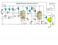
The below circuit is a model rocket igniter. Two 555's in monostable config, triggering the first 555 (u1) starts a delay, at the end of which U2 is triggered and launches a rocket.

It works well. But....

I've noted I get false triggering on power up, but only in U2. U1 has never shown this. I suspect this is due to the way U2's pin 2 is wired up.

I do run the circuit from 12V, rather than 6V as suggested by the author, and here is one unusual part - if I set my bench PSU to 12.2 or lower, triggering does not occur. If I set it higher, like 12.8 or above (like a fresh lead acid battery), U2 triggers on power up every time.

I have added some interlocks to stop an accidental launch, but would still prefer the false triggering was not occurring.....

Should I change anything in the circuit to help this??

Thanks in advance....
Lee
 

Attachments

ericgibbs

Joined Jan 29, 2010
18,872
hi Lee
Try increasing C9 and C12, on the power up Reset pins of the 555s, say 2.2uF or 4.7uF
E

EDIT:
Considering it only happens on U2, try C12 at 2.2uF or 4.7uF
 
Last edited:

tracecom

Joined Apr 16, 2010
3,944
The first thing I would try is the addition of a .1uF capacitor from pin 1 to pin 8 of both 555s. Place the capacitors as physically close to the pins as possible. Sometimes, the best way is to either place the caps on the bottom of the PCB directly attached to pins 1 and 8, or to have the caps straddle the IC on top of the PCB.
 

Wendy

Joined Mar 24, 2008
23,429
The first thing I would try is the addition of a .1uF capacitor from pin 1 to pin 8 of both 555s. Place the capacitors as physically close to the pins as possible. Sometimes, the best way is to either place the caps on the bottom of the PCB directly attached to pins 1 and 8, or to have the caps straddle the IC on top of the PCB.
That was going to be my suggestion. It also wouldn't hurt to have a decent cap (say 220uF) across the power supply.
 

Thread Starter

samuel.whiskers

Joined Mar 17, 2014
95
Thanks Gents.... I'll give these a try.... I've got it all done on stripboard, installed in its box, will try the caps across 1&8 first, no need to change anything over then.

Are ceramics OK for this??

Bill - There is a 47uF cap across the PSU, should I increase this to something like 220uF??
 

#12

Joined Nov 30, 2010
18,224
Ceramics are for the high frequencies that electrolytic caps can't reach. You need one of each when chasing a fast glitch.
 

Wendy

Joined Mar 24, 2008
23,429
Try the 0.1uF ceramics first. If it still does it then go for the 47uF to 220uF. The idea is to stabilize the power supply from transients.
 

Thread Starter

samuel.whiskers

Joined Mar 17, 2014
95
Am I correct in implying that as U2 triggers on power up, that U2 pin 2 is seeing a low voltage at that time? I did note with my first board of this circuit, when I accidentally put a 10uF at C10 instead of 1uF, it was much worse, and would trigger at a lower start-up voltage.

I will try these remedies tonight and report back....
Might be time to venture into LiPo batteries too, just use an 11.1V and solve everything in one swoop! :) Would still bug me though!
 

Wendy

Joined Mar 24, 2008
23,429
I am exceedingly familiar with the 555. This design is incomplete, I suspect you have (or were meant to have) a count down timer with it.

Let's go through the design...


U1 is a standard monostable design, and it is set for 38.8 seconds.

555 Monostable

Both 555s have a built in delay using R4/C9 and R8/C12 that will keep them off for less than 0.1 seconds. I would not have bothered, that or bumped the caps to much larger values to lengthen the enable times (note, the 555s do not turn on, they just enable). While the reset pin is low the output of the 555 is off, and it should not be able to trigger.

So you trigger U1 with a low pulse, it times out in 39 seconds, and the low edge pulse triggers U2. Again, this is a standard mono design set for 2.2 seconds.

The design is a bit clunky, there are a lot of extra parts I would not have used, but it is functional.

The false triggering is likely caused by power supply glitches. Bumping up C9 and C12 by a factor of 100 would slow the turn on to about 5 seconds. It is odd that they are false triggering, one of the hallmarks of the 555 is immunity from this kind of nonsense. It is possible the batteries are still charging the power supply cap when the reset pin goes high.
 

Attachments

Last edited:

Thread Starter

samuel.whiskers

Joined Mar 17, 2014
95
Thanks Bill...
The original circuit is here -
http://www.sentex.ca/~mec1995/gadgets/rocket.html

I left out U3 because I didn't want the beeping....

The full circuit I've used actually does use a third 555 in the exact configuration as U1 in this circuit, in parallel, separate to these two, it drives a relay to isolate the base of the transistor. It is the same circuit as U1 (with different timing RC), and does not trigger on power up. My way of ensuring no unwitting rocket launches, as you need to temporarily arm the system prior to starting the countdown....
 

Thread Starter

samuel.whiskers

Joined Mar 17, 2014
95
Well.... fixed!
I took a hybrid approach to the advice kindly offered by everyone - I changed out C12 for a 10uF to replace the 1uF. I also added a 0.1uF ceramic in parallel with the 47uF electrolytic.
Problem disappeared. I even used my 13V full-to-the-brim SLA battery to test....

Many thanks for the advice offered by everyone. It is very much appreciated.
Lee
 

ericgibbs

Joined Jan 29, 2010
18,872
hi Lee,
Its good to get positive feedback from an OP, more often we do not hear how a project responded to treatment.:rolleyes:

Thanks
E
 
Top