52 year old tube CB transceivre has ~50VAC chassis to gnd. Can't locate reason. Also noise from internet router.

Thread Starter

Darkstar

Joined Sep 3, 2010
177
I'm overhauling a 52 yr old tube CB Knight Kit transceiver. Noise suddenly showed up. I began replacing electrolytic caps and diodes. It helped the overall background noise level but not the pulsed noise. The noise sounds like static bursts about 50 Hz & is loud enough to drown all but the strongest signals. Noise traced to internet router. ATT told me how to change settings in router but that didn't help yet noise disappears when router is turned off. It transmits the noise all over the house. They are currently stumped over the noise frequency and its transmission. I've put ferrites and RFI filters all over but nothing helps. The noise is present only when the antenna is plugged in. I can use help here.

Since I began replacing the old caps in the radio, I've noticed that I can have anywhere from 27 to 68 VAC from chassis to gnd. It varies when I change caps. Maybe the ones I'm swapping in are as bad as the originals. I don't know a good way to measure leakage. They seem pretty good when I try. I can't find any caps that may be leaking to gnd as the possible source of the chassis voltage. I don't know if the chassis voltage was always there or not as I'd never measured it. I replaced the 2 wire power cord with a 3 wire and that's when I noticed this voltage. It can also show up on my antenna when I transmit. It should be on the antenna via the coax shield but I once measured nothing unless I transmitted. That has me stumped. I need help here also.

One non-polarized electrolytic capacitor in the power supply has a value of 0.12 uF, 600 VAC. I was wondering why a big electrolytic paper cap would be used when a small ceramic cap can give 0.12 uF at 1KV & save space? What's the advantage of using electrolytic over ceramic. The radio runs fine with ceramics in its place.

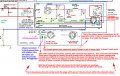
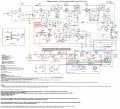
In general, the tubes seem good though reception and transmission seem a bit weak. (I should be getting a transmission voltage of about 15 volts but with the chassis voltage as it is I can have 50 volts measured as my output.) I could use help adjusting the tuning range to match the manual dial. I'm attaching a copy of the schematic.
 

Attachments

schmitt trigger

Joined Jul 12, 2010
897
When you mean measures from chassis to ground, you mean earth ground, correct.

Old transformers ere impregnated with shellac, a substance that eventually degrades It could be transformer leakage. Not saying this is it, but is always a possibility

Let's do something....put a 1k resistor between the chassis and the earth ground. Measure the voltage across. You can calculate the leakage current afterwards. The current, not the voltage is what matters. It could be a very tiny current, but with your DMM's 10 Meg impedance it translates into a very large voltage. That is why 1k would give you a better measurement.
 

Dodgydave

Joined Jun 22, 2012
11,302
The circuit uses a Transformer to isolate it from the mains, as you say you have replaced the mains lead from 2 wire to 3 the chances are you have introduced mains hum by using the Earth wire , try removing the earth wire and see what happens.
 

Thread Starter

Darkstar

Joined Sep 3, 2010
177
When you mean measures from chassis to ground, you mean earth ground, correct.

Old transformers ere impregnated with shellac, a substance that eventually degrades It could be transformer leakage. Not saying this is it, but is always a possibility

Let's do something....put a 1k resistor between the chassis and the earth ground. Measure the voltage across. You can calculate the leakage current afterwards. The current, not the voltage is what matters. It could be a very tiny current, but with your DMM's 10 Meg impedance it translates into a very large voltage. That is why 1k would give you a better measurement.
Thanks, I'll try that resistor. Maybe I can check for leakage between the transformer windings and case? Yes I meant earth ground. I meant to add that it doesn't sound like 60 Hz hum, it sounds like discrete static pulses. It wasn't present when I turned the radio on but appeared about a day later. It fades in and out like that. I thought I fixed it a couple times. It also has nothing to do with the caps I replaced or the ones I removed.
 
Last edited:

Thread Starter

Darkstar

Joined Sep 3, 2010
177
The circuit uses a Transformer to isolate it from the mains, as you say you have replaced the mains lead from 2 wire to 3 the chances are you have introduced mains hum by using the Earth wire , try removing the earth wire and see what happens.
The noise is unchanged regardless of ground connection. This does not sound like 60 Hz hum, it sounds like discrete pulses of static and it sounds a little slower than 60 Hz. It also fades in and out every few days it seems. Besides, it disappears when the router is turned off or the antenna is disconnected. The router doesn't have to be connecting anything to the net, just turned on and in standby mode is enough to blast the noise.
Just in case anyone wonders, the noise and chassis voltage are independent.
 

KeithWalker

Joined Jul 10, 2017
3,091
If you have the 3 pin power cable wired correctly, according to the diagram the chassis should be connected directly to supply ground. With the power cord unplugged, measure the resistance between the ground pin on the plug and the chassis ground. If does not show an extremely low resistance, start checking for continuity.
Regards,
Keith
 

schmitt trigger

Joined Jul 12, 2010
897
With respect to you question of replacing the paper 0.12uf/600VAC paper cap with ceramics:

Paper capacitors have much higher AC ripple ratings than ceramics. My advise is don't change it, unles you can prove it is defective.
 

Thread Starter

Darkstar

Joined Sep 3, 2010
177
If you have the 3 pin power cable wired correctly, according to the diagram the chassis should be connected directly to supply ground. With the power cord unplugged, measure the resistance between the ground pin on the plug and the chassis ground. If does not show an extremely low resistance, start checking for continuity.
Regards,
Keith
Pin 3 on the radio's original power connector is connected to the chassis. This isn't used for anything in AC mode, only when the DC power cord is used. As it is there is no specific connection for ground when run on AC so for now I use an alligator clip from the power cord's ground wire to the chassis. This is where I measured the voltage.
 

Thread Starter

Darkstar

Joined Sep 3, 2010
177
If you have the 3 pin power cable wired correctly, according to the diagram the chassis should be connected directly to supply ground. With the power cord unplugged, measure the resistance between the ground pin on the plug and the chassis ground. If does not show an extremely low resistance, start checking for continuity.
Regards,
Keith
I'm sure there is good continuity between the chassis and earth ground via the new power cord.
 

Thread Starter

Darkstar

Joined Sep 3, 2010
177
With respect to you question of replacing the paper 0.12uf/600VAC paper cap with ceramics:

Paper capacitors have much higher AC ripple ratings than ceramics. My advise is don't change it, unles you can prove it is defective.
I didn't know that about paper caps. I can replace it but I notice no difference with the ceramics, using 0.2 to 0.3 uF (I boosted the uF a bit because of the physical size difference.) I did not notice any difference in the voltages on the power supply caps when using these ceramics. 0.12 uF seems awfully small to provide much ripple suppression so that made me wonder too. Thanks.
 

KeithWalker

Joined Jul 10, 2017
3,091
I'm sure there is good continuity between the chassis and earth ground via the new power cord.
If there is good continuity between the chassis and the power cord ground pin, where exactly are you measuring between to get that voltage?
It would appear that the power outlet ground pin is not connected to ground!
Regards,
Keith
 

Dodgydave

Joined Jun 22, 2012
11,302
Pin 3 on the radio's original power connector is connected to the chassis. This isn't used for anything in AC mode, only when the DC power cord is used. As it is there is no specific connection for ground when run on AC so for now I use an alligator clip from the power cord's ground wire to the chassis. This is where I measured the voltage.
Can you mark on the diagram where you are measuring the AC voltage please, it sounds like you are trying to measure across the primary to secondary windings?
 

KeithWalker

Joined Jul 10, 2017
3,091
If the voltage between chassis and ground drops appreciably when a resistor is connected between them, then the leakage current is very low and is nothing to worry about. Keep the chassis grounded for safety.
You mention that the noise from the router is being picked up all over the house. Is that just with this transceiver or with other electronic devices?
If it is just interfering with this transciever, is it worse on any particular channel?
Regards,
Keith
 
Last edited:

Thread Starter

Darkstar

Joined Sep 3, 2010
177
Thanks, I'll try that resistor. Maybe I can check for leakage between the transformer windings and case? Yes I meant earth ground. I meant to add that it doesn't sound like 60 Hz hum, it sounds like discrete static pulses. It wasn't present when I turned the radio on but appeared about a day later. It fades in and out like that. I thought I fixed it a couple times. It also has nothing to do with the caps I replaced or the ones I removed.
I measured 48.3 VAC between the chassis and earth ground (ground wire on 3 wire power cord). Then I put a 1K resistor between them and measured 23.3 mV across it. The current is so low I can hardly feel it. It may have always been there and I wouldn't have known.
 

KeithWalker

Joined Jul 10, 2017
3,091
That's a very low leakage current and nothing to be really concerned about.Just keep the chassis grounded for safety.
Do you have an oscilloscope? If you do, connect a meter or two of wire to one of the inputs and see if you can pick up any of that strange signal. If you can see it, it may give you some clues. See if you can get a rough idea of its frequency.
Keith
 

Thread Starter

Darkstar

Joined Sep 3, 2010
177
If the voltage between chassis and ground drops appreciably when a resistor is connected between them, then the leakage current is very low and is nothing to worry about. Keep the chassis grounded for safety.
You mention that the noise from the router is being picked up all over the house. Is that just with this transceiver or with other electronic devices?
If it is just interfering with this transciever, is it worse on any particular channel?
Regards,
Keith
I pick up the router noise with the CB very loudly but I can pick it up a little on a regular, though old, AM-FM radio also just in certain places, and faintly. I have a newer transistorized CB which does not pick up the noise at all with the same antenna, etc. It is fairly uniform across the 23 channel range, but seems lately to be stronger between 12 and 23. The noise is not affected by the volume setting, it is reduced when the ANL is switched on or the Squelch is used. It can be picked up occasionally very faintly without an antenna such as if the antenna terminals are touched. The ATT repairman described his noise as sounding like a helicopter. He was speechless when I said mine sounded like it was 40-50 Hz, Also, his only was heard if an appliance with a speaker was right next to it. It would drop off quickly.
Can you mark on the diagram where you are measuring the AC voltage please, it sounds like you are trying to measure across the primary to secondary windings?
The sound became more static-y when I replaced the diodes with newer. It was essentially gone for 1 day then came back while I wasn't using the radio.

I've attached part of the schematic with notes about the grounds and where I measure the voltage.
Can you mark on the diagram where you are measuring the AC voltage please, it sounds like you are trying to measure across the primary to secondary windings?
 

Attachments

Thread Starter

Darkstar

Joined Sep 3, 2010
177
That's a very low leakage current and nothing to be really concerned about.Just keep the chassis grounded for safety.
Do you have an oscilloscope? If you do, connect a meter or two of wire to one of the inputs and see if you can pick up any of that strange signal. If you can see it, it may give you some clues. See if you can get a rough idea of its frequency.
Keith
I don't have a scope but my DMM can give freq data so I can try that (though most of the time it jumps around so much it is useless.)
 

KeithWalker

Joined Jul 10, 2017
3,091
Older analog AM receivers have an IF frequency of 455 to 470 KHZ which is the same as this transceiver. Whatever is causing the interference is probably breaking through the IF amplifier. That is why I suggested trying to determine the frequency of the interference.
Regards,
Keith
 

Thread Starter

Darkstar

Joined Sep 3, 2010
177
Older analog AM receivers have an IF frequency of 455 to 470 KHZ which is the same as this transceiver. Whatever is causing the interference is probably breaking through the IF amplifier. That is why I suggested trying to determine the frequency of the interference.
Regards,
Keith
I'll let you know what I find.
 

Thread Starter

Darkstar

Joined Sep 3, 2010
177
Older analog AM receivers have an IF frequency of 455 to 470 KHZ which is the same as this transceiver. Whatever is causing the interference is probably breaking through the IF amplifier. That is why I suggested trying to determine the frequency of the interference.
Regards,
Keith
As expected my meter was all over the place but I did get 2 different relatively steady readings. Holding the meter probe on the back of the router I got numbers that were constantly changing, but stayed between 30 Hz and 60 Hz. The second reading was when I touched the probe to the shield of one of the cables coming out of the router. Those numbers stayed between 600 KHz and 700 KHz. I got nothing by trying to use an antenna wire to pick up a signal. I have an inductive pick up for finding live wires. It should have had no trouble picking up the signal. This picks up the signal easily on the CB circuit but I got nothing here. Surprising.

The only thing that changed the sound of the pulses was when I changed the diodes. They went from being clean individual pulses (old diodes) to being individual pulses covered with static (newer diodes, still rectifier diodes but larger.)

I can record the sound from the CB but it would be either a .MOV file or a .AMR file. I can't switch them to MP3 files. I'll try right now... Nope, I get an error msg that the file does not have an allowed extension (.MOV).

P.S. Can you explain what you meant by 'Whatever is causing the interference is probably breaking through the IF amplifier.'? Do you mean a similar frequency may be breaking into the IF amp from the outside? Or interfering with the IF amp from the inside because of the similar freq?
 
Last edited:
Top