
hello friends
I'm completely new to battery packs and I'm planning to make one of 4S2p configuration for my portable speaker project and i have some questions related to it.
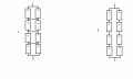
Qn. 1) I have bought 8 Li ion cells of 5800mAh each but I'm confused how to arrange the battery pack. 2 arrangements are shown in the pic and I heard that method 1 is good since its easy for balancing for the BMS, but will it be lacking anything when compared to method 2 in terms of total capacity or anything??
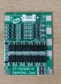
Qn. 2) I have bought a BMS for the project (shown in the pic) which has balance protection in build, I guess P+, P- are connected to load, B+, B- to the end terminals of the battery. but I'm confused with its terminals B 1,B2,B3. from where should i number the cells ??
Qn. 3) This is the problem that worries me a lot. I want to charge the pack with a 12v DC wall adapter, but I understand that the battery should be charged in CC mode and then CV mode. Since i use a 12V charger I'm suppose charge with 4.2 X 4 = 16.8 V with the help of a boost module. Unfortunately I can't find a CC, CV boost module instead could only find a CC, CV buck module. so I'm planning to first use a boost module with only CV mode to get the 16.8V or higher and then fed as the input for the CC, CV buck module to finally use it as the charging source for the batteries. MY question is would this arrangement works or not??
Qn. 4) So if the above arrangement in Qn. 3 works then, what should be the charging current that should be set on the module??
I'm completely new to battery packs and I'm planning to make one of 4S2p configuration for my portable speaker project and i have some questions related to it.
Qn. 1) I have bought 8 Li ion cells of 5800mAh each but I'm confused how to arrange the battery pack. 2 arrangements are shown in the pic and I heard that method 1 is good since its easy for balancing for the BMS, but will it be lacking anything when compared to method 2 in terms of total capacity or anything??
Qn. 2) I have bought a BMS for the project (shown in the pic) which has balance protection in build, I guess P+, P- are connected to load, B+, B- to the end terminals of the battery. but I'm confused with its terminals B 1,B2,B3. from where should i number the cells ??
Qn. 3) This is the problem that worries me a lot. I want to charge the pack with a 12v DC wall adapter, but I understand that the battery should be charged in CC mode and then CV mode. Since i use a 12V charger I'm suppose charge with 4.2 X 4 = 16.8 V with the help of a boost module. Unfortunately I can't find a CC, CV boost module instead could only find a CC, CV buck module. so I'm planning to first use a boost module with only CV mode to get the 16.8V or higher and then fed as the input for the CC, CV buck module to finally use it as the charging source for the batteries. MY question is would this arrangement works or not??
Qn. 4) So if the above arrangement in Qn. 3 works then, what should be the charging current that should be set on the module??
Attachments
-
 246.4 KB Views: 25
 -
 28.4 KB Views: 24


