4017 clock osc

Thread Starter

sheldons

Joined Oct 26, 2011
613
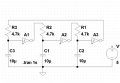
heres a simple clock osc for driving 4017s etc which can be built quite small and the value of the timing components can be altered to suit .
 

Attachments

ScottWang

Joined Aug 23, 2012
7,501
using NC7S14 or NC7SP14 to generate the square wave, it really can make the PCB smaller.

But I having use this IC yet, the IC I were used to generate clock, crystal osciilator, 7414, 74HC14, MC14584, 74LS04, CD4060, CD4011,CD4093,CD4069,NE555...
 

Thread Starter

sheldons

Joined Oct 26, 2011
613
this circuit i built and used as a clk osc for a 4017 circuit i built a while back as at the time i had ran out of 4093s and very rarely bother with 555s to clock 4017s so used what i had at the time and it works well
 

Thread Starter

sheldons

Joined Oct 26, 2011
613
well i mostly use a 4093,1 gate ,1 resistor one capacitor and there is your clk osc...but as i had none available at the time this is what i used.....
 

takao21203

Joined Apr 28, 2012
3,702
Blinking LED circuits and police sirens with NE555 are totally hobby circuits- and they exist for quite a long while.

Most students are well aware of PICs and the so-called Arduino.

If one wanted a clock base, a PIC is used. Not many people want large capacitors these days or potentimeters. Pushbuttons are much better and it is done with software.

If you have too many 1489 serial receivers, or inverter gate chips, you can use these too. Any odd number will oscillate. It is a waste though, as with a PIC you don't need the capacitors, and a cheap one will be enough for that.
 

Attachments

timescope

Joined Dec 14, 2011
298
I once made a clock out of an unused half of a 4013 D flip-flop using the set and reset inputs. Each had a capacitor to ground and a resistor to the Q and Q' outputs such that if Q was H, the reset capacitor charged etc. I think I added diodes in parallel with the resistors to discharge the capacitors rapidly once the threshold was crossed.

Timescope
 
Top