40 Days shipping. need a second eye to make sure It won't be 160 days!!

Thread Starter

kam hagh

Joined Nov 7, 2015
60
So I designed a smart nightstand (after a week up staying up late and wasting so many hours.... I'm only 18 and self taught don't judge me :c)

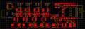
This is the circuit. I assume I"m just gonna connect some jumpers to the pins and program the esp12E.

Did I do anything wrong? I mean this is gonna take up to 40 days to arrive I would be devastated to reorder it.
Thanks for your help!

I made it On EasyEDA!

After so many attempted and time I said screw it and used auto router though!

EDIT: Right image uploaded!

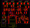
This is the schematic
Screenshot (15)_kam hagh_988x790.gif
 

Attachments

Last edited by a moderator:

WBahn

Joined Mar 31, 2012
30,055
How can we possibly know if anything is wrong?

Even if we wanted to back out the schematic, we have nothing to compare it to. Plus not all of the trace routing is visible.

How could we know if you have power, current handling, thermal, or EMI issues?

It does look like you have some inefficiently routed tracks.
 

Thread Starter

kam hagh

Joined Nov 7, 2015
60
How can we possibly know if anything is wrong?

Even if we wanted to back out the schematic, we have nothing to compare it to. Plus not all of the trace routing is visible.

How could we know if you have power, current handling, thermal, or EMI issues?

It does look like you have some inefficiently routed tracks.
Does the schematic I linked help?
The thing I"m worried most about is the inductor for the Step down. I didn't understand anything so I used the example's value!
 

Thread Starter

kam hagh

Joined Nov 7, 2015
60
The output voltage from U2 doesn't appear to be connected to anything on the schematic or PCB (which I presume is the step down you refer to).
You just saved my life!

I'm starting to believe in disabled or something. I don't know why I keep making mistakes even if I try hard to look for them
 

WBahn

Joined Mar 31, 2012
30,055
The tool you are using should have the ability to perform LVS (layout-vs-schematic).If so, take the time to learn how to use it. If not, find a tool that does.
 

philba

Joined Aug 17, 2017
959
Does easyEDA have a design rules check? This has saved more than one board for me.

To your inductor question, the part's datasheet should give you enough info to spec the max current the inductor will see. When in doubt, err toward higher amps.

Getting a board design perfect on the first try is hard. So, to get a usable pcb, I would anticipate errors. Leave enough room to cut/jumper traces. Maybe make the traces wider so you can solder wires to them. Board designers often talk about "blue wire boards" - boards that have been hacked up to get working.

I feel for you. 40 day turn time would probably drive me back to etching my own.
 

Thread Starter

kam hagh

Joined Nov 7, 2015
60
Does easyEDA have a design rules check? This has saved more than one board for me.

To your inductor question, the part's datasheet should give you enough info to spec the max current the inductor will see. When in doubt, err toward higher amps.

Getting a board design perfect on the first try is hard. So, to get a usable pcb, I would anticipate errors. Leave enough room to cut/jumper traces. Maybe make the traces wider so you can solder wires to them. Board designers often talk about "blue wire boards" - boards that have been hacked up to get working.

I feel for you. 40 day turn time would probably drive me back to etching my own.
Thanks a lot people! You are all Amazing!

I did etch a pcb only once and got surprisingly good results (everything was fine, 16 mil traces) but I imagine double sided is going to be very hard. Also I ruined both my pants and kitchen!!
 

Thread Starter

kam hagh

Joined Nov 7, 2015
60
Does easyEDA have a design rules check? This has saved more than one board for me.

To your inductor question, the part's datasheet should give you enough info to spec the max current the inductor will see. When in doubt, err toward higher amps.

Getting a board design perfect on the first try is hard. So, to get a usable pcb, I would anticipate errors. Leave enough room to cut/jumper traces. Maybe make the traces wider so you can solder wires to them. Board designers often talk about "blue wire boards" - boards that have been hacked up to get working.

I feel for you. 40 day turn time would probably drive me back to etching my own.
there was an equation I didn't understand anything about it. in my deference it was 2am I'll check it after I had my morning coffee!!!

and it does have some design checks ( smd clearance and all that) I used to use Eagle before they made my country forbidden. I'll use it with a vpn though as I used to love eagle to death :p it's very powerful and nice. I can just upload the final board to their website!
 

AnalogKid

Joined Aug 1, 2013
11,042
Not to be picky or anything, but you question lacks substance - any substance.
What is a "smart nightstand"?
What is the overall project?
What is the overall circuit supposed to do?
What are its inputs and outputs?
What does each circuit section do?
What is the power source?
Please post the datasheets for each IC.

ak
 

Thread Starter

kam hagh

Joined Nov 7, 2015
60
Not to be picky or anything, but you question lacks substance - any substance.
What is a "smart nightstand"?
What is the overall project?
What is the overall circuit supposed to do?
What are its inputs and outputs?
What does each circuit section do?
What is the power source?
Please post the datasheets for each IC.

ak
well it's basically a WiFi controlled LED. I'm planning to put a clear flower pot that looks really pretty on top of it (it's clear) and write an android app that tells it to turn on when I get home and off when I'm not etc. it's basically useless gimmicks but the main thing I want it to do is to turn off with my Phone and maybe change color when I get a notification or shine a specific color in the morning!

the circuit is supposed to drive 4 LEDs with 150ma for each color and the white is unknown for now but I just put a bunch of 0.5w leds in series and parallel to make them consume almost the same at 9.8v~
that's all. it's just gonna be connected to power and the code on the ESP32 will give the driver IC a pwm based on the code.

the bottom right is basically the 3.3 step down for my IC (I couldn't bring myself to waste 1w of heat using a linear one. although if I write my code efficiently it's gonna consume that for only a few milliseconds every now and then but still.... (also I asked my gf for opinions and she said make it switching to show off my "skills" (by skills she means reading a few lines and changing values accordingly)

the input is only a 12v in, the headers are there for the leds to be soldered to. I won't actually put headers in there. the power source is an 12v 1a or 2a adapter. (haven't calculated the total power draw yet but i guess it's 1a~ since other components barely pass 500ma together


Step down datasheet:
http://aosmd.com/res/data_sheets/aoz1280ci.pdf

the MCU datasheet:
http://www.kloppenborg.net/images/blog/esp8266/esp8266-esp12e-specs.pdf

The LED Driver Datasheet:
https://people.xiph.org/~xiphmont/thinkpad/PT4115E.pdf
 
Last edited:

Thread Starter

kam hagh

Joined Nov 7, 2015
60
Post a photo of your PCB - I’d like to see your success. Also, a picture of your kitchen!
There you go ^_^

that was 2.5 years ago... wow... that's kinda... sad!

the kitchen is hard to tell from a camera. it's just a yellowed area. not by much. there's a gold line on my jeans too. also my kitchen is messy I'd have to move a lot of dishes to take a picture :D
 

Attachments

Last edited:

GopherT

Joined Nov 23, 2012
8,009
There you go ^_^

that was 2.5 years ago... wow... that's kinda... sad!

the kitchen is hard to tell from a camera. it's just a yellowed area. not by much. there's a gold line on my jeans too. also my kitchen is messy I'd have to move a lot of dishes to take a picture :D
Buy a product like “iron-out” (sodium di-thionite) to remove the color from your kitchen. Don’t use it on your pants, it will make a hole.
 

Thread Starter

kam hagh

Joined Nov 7, 2015
60
Buy a product like “iron-out” (sodium di-thionate) to remove the color from your kitchen. Don’t use it on your pants, it will make a hole.
Jesus that's scary.... I already barely convinced myself to get near the etching acid (chloride something!?) also as you could guess from the whole not connecting my reg to anywhere thing I"m incredibly lousy so I rather not. I don't wanna get a mark on my skin or well.... dissolve myself
 

GopherT

Joined Nov 23, 2012
8,009
Jesus that's scary.... I already barely convinced myself to get near the etching acid (chloride something!?) also as you could guess from the whole not connecting my reg to anywhere thing I"m incredibly lousy so I rather not. I don't wanna get a mark on my skin or well.... dissolve myself
After a couple of holes in your skin, you start to learn to handle chemicals safely.
 

philba

Joined Aug 17, 2017
959
I bet you were using ferric chloride. Nasty stuff.

On your board, it looks reasonable though I wonder about your layout for the PT4115s. You definitely want wider traces for the switch loop (inductor to SW/Diode, Diode to Vin). The datasheet talks about a star ground - I don't see that in your layout. Also, I'd use a ground plane, probably on the bottom, to make for better noise immunity but still keeping to the star ground principals. I'd have to think about how to do that with multiple of the PT4115s, though.

BTW, I find it interesting that the PT4115 isn't available from mainstream distis but is all over amazon and ebay.
 
Last edited:

Thread Starter

kam hagh

Joined Nov 7, 2015
60
I bet you were using ferric chloride. Nasty stuff.

On your board, it looks reasonable though I wonder about your layout for the PT4115s. You definitely want wider traces for the switch loop (inductor to SW/Diode, Diode to Vin). The datasheet talks about a star ground - I don't see that in your layout. Also, I'd use a ground plane, probably on the bottom, to make for better noise immunity but still keeping to the star ground principals. I'd have to think about how to do that with multiple of the PT4115s, though.

BTW, I find it interesting that the PT4115 isn't available from mainstream distis but is all over amazon and ebay.
Yess exactly that. is there another solution safer? and tbh I have absolutely no idea what a star ground is but I'm googling. also I figured it's only 150ma :p although my white might consume more. but I'll change the sw trace to be bigger!

also I couldn't figure out how to make a ground plane as the software was acting weird (couldn't remove the part around trough hole parts so they don't short)

and yeah 4115 in theory atleast is a super cool IC! it only needs a few parts and rocks!
 
Top