4-Bit Computer

Thread Starter

Robin Mitchell

Joined Oct 25, 2009
819
Hi everyone,

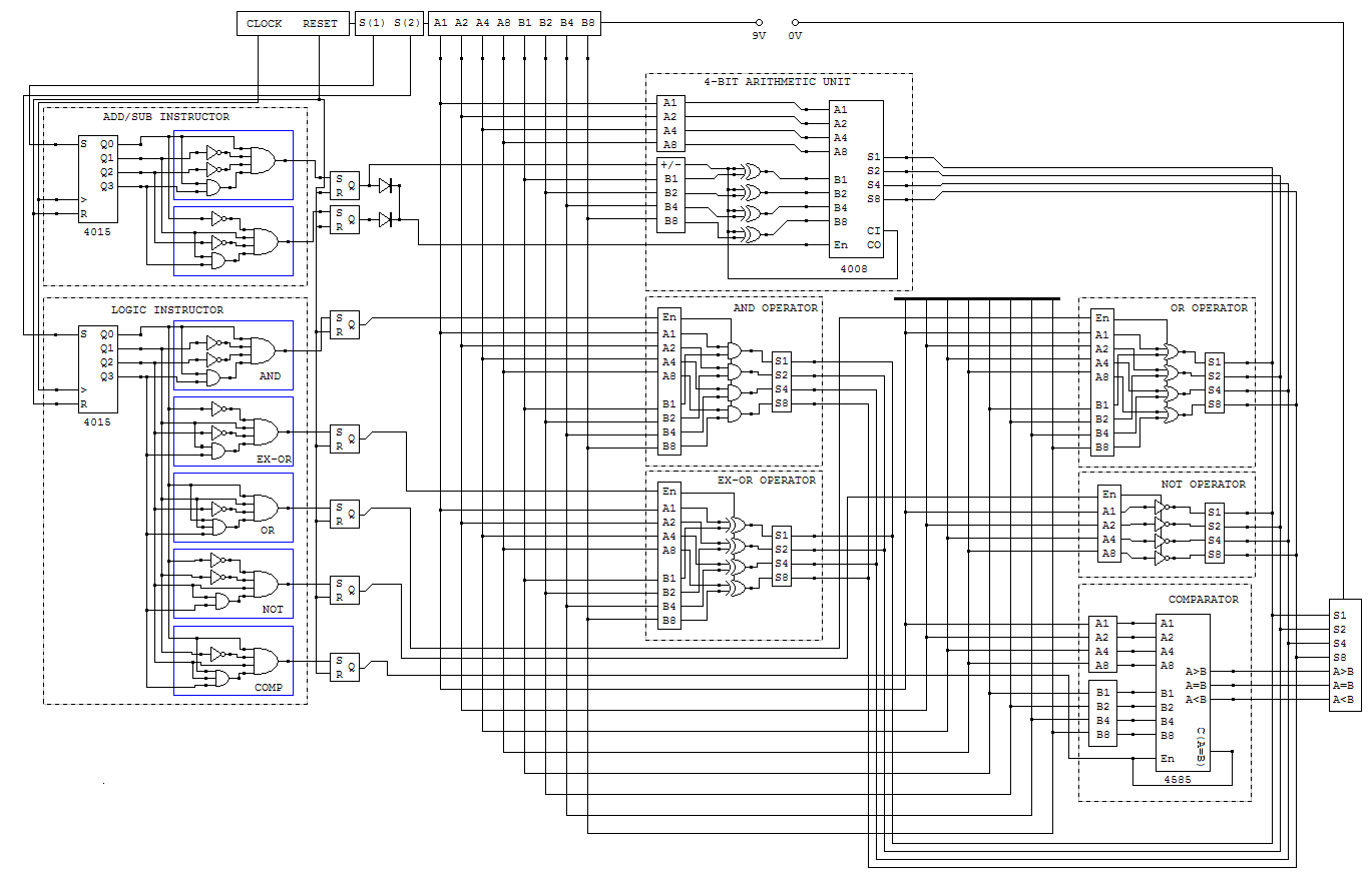
Before I get into details I just want to post this for ideas and suggestions. I am currently designing a 4-Bit computer that is fully programmable. I have the schematics for the ALU finished and now working on memory (RAM and tape drive). However, the schematics will be release once someone tells me how to get them protected from copying (this is my life’s work!).

Here is some info on how it works:

Memory - Tape recorder
I hijacked a microphone so it records a beep on the tape. This is one bit and I have used a 4017 (connected to a clock) to load data from the tape. For example, the data looks something like this:

0100100100001

Lets examine this:
0 | 1001 | 0010| 0001
The first number tells it to either do arithmetic or a logic instruction
The Next four numbers tell it to do a specific instruction (in this case addition)
The Next four numbers is the first 4 bit number and the last four numbers is the second 4 bit number. So in this case we do 2+1 which is 3 and this is 0011 in binary.


Logic instruction:

Anyone familiar with bite-wise operations, well this does AND, OR, NOT, EX-OR. I wont go into detail how it does it but I can give an example:

1100100100001

This will do the AND function. So, we have 0010 and 0001. The result is 0000.


This is all I can think of at the moment, please like it because my dad does not seem to be impressed :(

Thanks!!!
I will issues the schematics soon but not yet ;)
 

RiJoRI

Joined Aug 15, 2007
536
Well, I am impressed! A long, long time ago I took a micro course where we had to build a 4-bit CPU. It used an ALU and a number of latches.

Your project is a good way to learn the gizzards of a microcomputer. I would guess that your dad is less than overwhelmed because, realistically, this is off the trailing edge. It's good for learning, but I truly doubt you would need to copyright this -- there are 8-bit micros available for less than the individual parts for your 4-bitter, and the 8-bitters can do a whole lot more.

What I'm saying is that this is a good learning project, but don't look to retire from the sales. Especially since tape recorders are getting harder and harder to find. I would probably look into a serial EEPROM to store the programs.

Good luck!
--Rich
 
Post your ALU schematic, lets see what you've got to work with.

PS you can't protect images you post on the internet. Use the PNG format as jpg looks awful for schematics.
 
Last edited:

Thread Starter

Robin Mitchell

Joined Oct 25, 2009
819
This is it, i need to make some more changes as i want to add some more stuff :)
Note that I cant stand schematic programs, and thus draw them myself!!!!
 
I'm being serious. Nice work.

Remember to add 0.1uF caps across the power pins to every IC if you decide to build one.

I asked about microcontrollers because when I was 15 (1976) I wire-wrapped an 1802CPU called a COSMAC ELF
It was very exciting and I still have it somewhere.
But building a CPU from scratch is a very complex undertaking and unless you love to solder, wirewrap ot breadboard thousands of little tiny wires you might want to take a peek at microcontrollers. They make teeny weeny cheap 8pin devices with thousands of transistors for about the price of a couple of CMOS ICs.

Either way keep up the good work and you'll go far.
 

Thread Starter

Robin Mitchell

Joined Oct 25, 2009
819
A-ha!
Dont worry Lord Black Adder for I have a cunning plan,
The cowes high tech will etch some PCBS for me instead! He has also given me access to all their electrical stuff because they can teach it (no available teacher).

Ok, this question might make me look like an idiot in the electronic world, why do i need to add capacitors? is it to stop static electrical damage or overloads to the ic?
 

dag10

Joined Oct 10, 2009
7
Nice...

I'm planning on building one myself within the next few months.
Right now I'm building a smaller computer that just uses the Z80 processor.

Here's a great website that I'm using for reference (for the homemade CPU and the Z80 computer): http://www.cpuville.com

Read through it, and on the first page he posts a link to a PDF that's part of a book. I would advise reading it. You already understand how a CPU works, but I think you'll be less likely to make design errors after reading it. You also may think of enhancements!

Good luck!

:)
 

hgmjr

Joined Jan 28, 2005
9,027
...

Ok, this question might make me look like an idiot in the electronic world, why do i need to add capacitors? is it to stop static electrical damage or overloads to the ic?
If the capacitors you are refering to are bypass capacitors, then your question is definitely a valid one. It is important that you use bypass capacitors liberally. They are cheap insurance for keeping down the noise on your power supply lines. Quieter power supply lines means less potential for electrical noise from one device to cross-talk to another device over the power supply bus.

hgmjr
 

Thread Starter

Robin Mitchell

Joined Oct 25, 2009
819
Wow, now thats a circuit!!!

Oh, guys, do you think i should build my circuit on one borard or build it in sections and connect them up? Like one board for the AND logic and so on?
 

dag10

Joined Oct 10, 2009
7
For your circuit, I would use one board. Using multiple boards for your circuit will probably make it more complex, and wont help much.
 

beenthere

Joined Apr 20, 2004
15,819
For your circuit, I would use one board. Using multiple boards for your circuit will probably make it more complex, and wont help much.
That may not be good advice. The clock is made with multiple layers in the PCB. Even going double layer at home can be a major challenge.

Wire wrap is the way to go. It is the one technology that allows for reasonably easy changes in the circuit.
 

kubeek

Joined Sep 20, 2005
5,795
I think you could add a Work register to your alu, so that you can simplify your instructions. You can have for example 8 bit instruction, which lets you have 16 operations with one 4bit operand, and the second operand is the work register. This way your alu gets simpler, but it still has its functionality.

When you make this change to your design, you will have to add two instructions, one to read memory to the work register, and one to write the work register to some memory address.
You should also note that you can have for example more complex instructions, the amount of bits for instruction number and operand don´t have to be the same.
Example:
if the first bit is 0, it is an ALU instruction with one 4-bit operand, like 0xxx-DDDD, where xxx is instruction 0..7, and DDDD is 4bit value, like ADD DDDD to Work register
if the first two bits are 11, it can be an I/O instruction, R/W direction bit and 5-bit operand representing the memory location, like 11XD-DDDD - write W to DDDDD
if the first two bits are 10, it can be some other two operations like above (or more operations with less bits for operand)....
 

dag10

Joined Oct 10, 2009
7
That may not be good advice. The clock is made with multiple layers in the PCB. Even going double layer at home can be a major challenge.

Wire wrap is the way to go. It is the one technology that allows for reasonably easy changes in the circuit.
Oh, you're using PCB?
Sorry, I must have missed that...

Yeah, if you're trying PCB, it'll defiantly be hard on one board. And beenthere is right with wire-wrapping. It is defiantly the best prototyping technique. I'm using it for my Z80 computer and homemade CPU.
 

Thread Starter

Robin Mitchell

Joined Oct 25, 2009
819
wire wrapping looks very in-efficiant because, well i mean its hard to trace wires!!!

Also, an instruction like ADD, how could I impliment this so the user types ADD and it comes out as like 000?
 
Last edited:

SgtWookie

Joined Jul 17, 2007
22,230
You will likely find that when you go to route traces on a PCB, you'll have quite a rats nest to sort out. Using multilayer boards will help, but they're expensive to get made - and if you think tracing wires are hard, try tracing out routings that are buried inside a fiberglass PCB!
 
Top