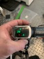
The seller said that because there was a defect in manufacturing it has to be returned that is why he sent me another piece of junk. FYI I applied both 36 volts and 40 volts to the new throttle and it still only reads empty
The seller said that because there was a defect in manufacturing it has to be returned that is why he sent me another piece of junk. FYI I applied both 36 volts and 40 volts to the new throttle and it still only reads empty
Amazon got involved and I gather the seller most likely won’t be listing products anymore on their site. They were selling mismatched surplus parts and had many complaints.
The conversation is interesting to me, but it seems funny (or can be dangerous) with some assumptions about batteries and circuits. The first was @MrChips saying "will show the battery voltage as 66%".. NO, the range of a "36v battery" is not 0.0V to 36V! Never discharge a lithium cell to 0V because it is damaging, maybe dangerous because of what it's doing inside. The 24v and 36v do not have the same voltage at 0% either.
Knowing the voltage range you need depends on both of their composition. Was the 24v battery a type of lithium? (could be lead-acid which has different needs and voltages). Even different lithium compositions have different specs. With Lithium (which may have between 3.2v and 3.7v cells) for example, you want to know how many cells are in series to add up to ~24 or ~36. The names 12/24/36/48 were based on original lead-acid cells which are a little over 2v each therefore closer to 12v divisible. That's why for lithium, a 24v may read nominal 25.6v if made with 3.2*8 (8 cells, 3.2v nominal each). That could then be charged up to 29.2v, each cell 3.65v (100%) and discharge to maybe 20V being 0% (each cell dead at 2.5V).
So if your "24v battery" has a range 20 to 29.2 and the "36v lithium" (assuming use 12 of same type cell in series) was charging from 30 to 42v (depends what they did expect and what it did charge for 100%)...
then at a 25v charge, the 36v system would measure completely dead or if possible, -42%: (25-30) / (42-30)
Perhaps a 36V battery can safely drop to around 25V, so the meter depends on what they designed it to do depending how much they want you to push it. With most Lithium, I recommend keeping it close around 50% if reasonably possible because the cells will last longer.
Now as far as "boosting" power, first I think that's overkill and would make my own cheap meter or buy one for the correct battery. Of course if boosting voltage, only send to the display meter, not to drive the motors because it doesn't magically increase power.
Instead of those costly boost converter modules, I like this simple circuit with diode and capacitors where you create a square wave (low fequency) of the battery voltage. Send to this doubler, https://en.wikipedia.org/wiki/Voltage_doubler
and then you can use resistors to drop to the desired % reading.
I appreciate everyone’s input on this matter. Just some clarification the batteries are two 12 volt 9ah lead acid batteries wired in series. The company sent me another throttle with a battery indicator and instead of it being 24 volts it is 48 volts. Seems these seller are just trying to sell their surplus junk. Amazon refunded my money and told me to keep the throttle. It would be nice if I could get it to work properly. The battery indicator is simply wired directly to a 24 volt source off the controller. This source is made for these types of battery indicators.
I'm glad you could keep the throttle part, so maybe we can still help get the level indicator working for the two 12v 9Ah SLA in series (are they AGM?).
You should also know, first of all, the range of voltage to expect from each battery. Full charge (no load) can read either 12.6 or if AGM, 13.0 and if reads higher, won't stay for long.
Some say you can discharge a 12v down to 10.5v, others say not less than 11v but realistically it helps to read the actual spec sheets and know what that manufacturer says. Plenty of articles also talk about a dark secret which of course isn't really kept secret: Never draw the full 9Ah capacity if it is called 9Ah, in fact only drain up to 50% of that (4.5Ah) because you are damaging it! If a battery is rated say 9 Amp Hours you might think it is simply that, but no. For one, it's damaged if you drain that much but There's more. You can't expect to draw 9 Amps and have it last an entire hour (which is what 9Ah should mean) because they rate that as a specific number of hours they took to drain it. For example if the fine print says 9Ah over 20 hours, they were only drawing 0.45A and that took 20 hours before it gave up. If you took more current, say 1A (not enough to drive a scooter), it would have significantly less Amp Hours rating. Maybe it could provide 2A but that's even worse on capacity. Still keep in mind that will also be damaging the battery because of trying to use full instead of half the rated capacity.
After you figure out those things, you can figure the voltages to test for, to say whether the capacity is currently at one of the four levels.
The batteries are 12V 9AH AGM HR series SLA. At full throttle it gives you 45 minutes of runtime. From what I can gather from different manufactures of these indicators a 24 volt system should have the following values:
23 V up, 4 LCD
23 V-22 V, 3 LCD
20 V-21 V, 2 LCD
20 V or less, 1 LCD
There is almost no room and no air flow in the scooter compartment for additional electronics. Between the controller (500 Watt) and the 2 batteries it is pretty tight quarters. The controller does has an output designated for an indicator.
Alright. We won't need a boost or other circuit from what I've seen, that was only if you can't open it up. I had looked more at the images and see that the important issues to check would be:
1. Power supply voltage to the LM339 (my old TI data sheet says can handle 2 to 36v, sounds easy)
2. Ensure the chips are working as expected. If correct voltages going in don't produce correct output, should replace the chip.
3. Ensure PCB connections are right for what we expect
4. Then just a matter of resistor values or otherwise mod the existing circuit.
The proper order of steps ensures we're not just guessing why something didn't do what we thought it should do with our new design. I know that I'm repeating what some have gone over, but something must have been missed or it would just work.
I'm assuming you have a volt meter.
Also assuming the wires come straight from battery.
I'm not sure what that transistor thing is yet (3-pin component) but if I figure out the layout, might help.
I may take a while to work this out but first question is what are the voltages on the batt wire and the chip pins, as well as what LEDs are on when measured... in order to see if the LM339 appears to work
unfortunately I don’t have a power source that is 48volts. I have a meter, soldering gun and a little experience in electronics but it has been along time since I’ve needed to work on anything like this! This largest power source I could locate is 40 volts and that triggers the low LED. Sorry I couldn’t be more helpful.
unfortunately I don’t have a power source that is 48volts. I have a meter, soldering gun and a little experience in electronics but it has been along time since I’ve needed to work on anything like this! This largest power source I could locate is 40 volts and that triggers the low LED. Sorry I couldn’t be more helpful.
Well the saga continues. I ordered another 24 volt controller with throttle from Amazon. The controller is 24 volts but the throttle also ends up to be 48 volts. It is even stamped 48 volts on the unit. I guess there must be an excess supply of these 48 volts throttles! The seller refunded my money and told me to keep the stuff, they said it isn’t worth returning to China. I wonder if this one could be modified to read 24 volts. I’ve attached a photo of the circuit board
Sorry me again! Well the saga continues. I ordered another 24 volt controller with throttle from Amazon. The controller is 24 volts but the throttle also ends up to be 48 volts. It is even stamped 48 volts on the unit. I guess there must be an excess supply of these 48 volts throttles! The seller refunded my money and told me to keep the stuff, they said it isn’t worth returning to China. I’ve attached a photo of the circuit board. Also did some research and from what I can gather from different manufactures of these indicators a 24 volt system should have the following values:
23 V up, 3 LED
23 V-22 V, 2 LED
20 V-21 V, 1 LED
This is same circuit board as the previous 36 volt throttle that I had to send back which I was able to modify with the 24K resistor. Are you able to suggest a modification so it would read 24 volts (Actually 25.8 volts)?
 Facebook
 Google
 GitHub
 Linkedin