
The 9 wire drawing are both star connections. Low voltage the phase windings are in parallel and series for high voltage. The drawing shows Delta. That is incorrect.Having some trouble posting Pictures but this should help
Thanks for all you help
3 Phase Water Pump Problems!!
- Thread starter Dfry
- Start date
Scroll to continue with content
This should be wired in Delta AFAIK unless the motor nameplate gave you some indication otherwise. Can you post a pic of the motor wiring diagram?
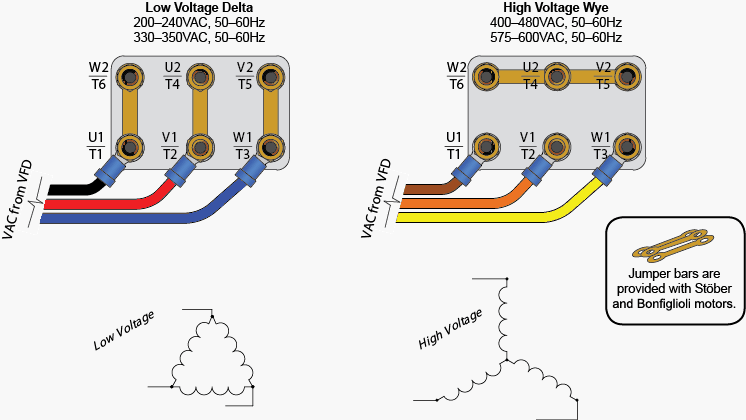
The voltages shown here are strange. A 200 volt winding connected Star will result in 346 volts. (200 x 1.73) Delta here is 200 volts phase to phase. Star it is 346 volts phase to phase. This motor has a single winding only per phase. No parallel or series possibilites. I've seen this arrangement but I don't think it's common.
GetDeviceInfo
- Joined Jun 7, 2009
- 2,196
more common in industry with wye/delta starting schemes.
If the diagram I posted is showing incorrect cable connections, then what is the correct conjunction of cables to get the appropriate amount of voltage to each phase. I understand that each phase should be in a parallel so I need to make it a star connection?The 9 wire drawing are both star connections. Low voltage the phase windings are in parallel and series for high voltage. The drawing shows Delta. That is incorrect.
This is correct for the usual Star connected 3 phase motor. It has one internal permanent star point. It can't be connected Delta unless you find and open that internal star. Those leads brought out would then be marked 10, 11, 12. See the attached sketch. A Google search should turn up many illustrations. Notice how the numbers start at 1 and spiral inwards to end at 12. Our instructors referred that to the Zulu bird. Flies around in ever decreasing circles until it disappears up it's own asshole. lol If you remember this drawing you can easily connect any 9 or 12 lead motor in Star or Delta for either low or high voltage with out any reference.Hello All,
I am putting this out there for anyone who may have a definitive answer for my problem. I am currently trying to install a U.S. standard 3 Phase water pump for my living facilities, But our site is powered by a European standard (220v / 50Hz) generator. The generator has a Bus bar setup with an output of 220v. The pump is a (208-230v / 440-480v / 60Hz) Pump.
When I wired the pump for Low "Y" Voltage Transmission the pump started to smoke immediately but the pump was moving for a short period of time. I am curious to find out if there are any alternatives or suggestions that might help me understand why 220v will not work on this pump??
the wiring diagram for "Y" or low voltage transmission is below:
Phase1 to 1 and 7
Phase2 to 2 and 8
Phase3 to 3 and 9
leaving 4,5, and 6 tied off together
The sketch
Attachments
-
 81.1 KB Views: 33
We had a problem with efficiency at the air coditioning manufacturing plant whereh I worked. We had to install 50 hz generators at every run test station, on every line that produced 50 hz units.
The company initially tried to run them at 60 hz but were not satisfied with the results, I wasn't privvy to particulars since I was a lowly Maintenance Man.
The units did run, just not as well as intended.
The company initially tried to run them at 60 hz but were not satisfied with the results, I wasn't privvy to particulars since I was a lowly Maintenance Man.
The units did run, just not as well as intended.
It sounds like everything is wired correctly.
To verify:
If you did test it with water following the instructions in the manual for open/closed systems and it smoked, then your best bet is to contact the manufacturer.
To verify:
- The voltage across red-black is ~225VAC.
- The voltage across gray-black is ~225VAC.
- The voltage across red-grey is ~225VAC.
- Wires 4, 5, & 6 on the motor are tied together.
- Wires 1 & 7 on the motor are tied together and connected to red-black through the motor starter.
- Wires 2 & 8 on the motor are tied together and connected to grey-black through the motor starter.
- Wires 3 & 9 on the motor are tied together and connected to red-grey through the motor starter.
If you did test it with water following the instructions in the manual for open/closed systems and it smoked, then your best bet is to contact the manufacturer.
well first of all if you are talking about bridging the legs across each other; its not possible due the the power output configured on the bus bar. What you are refering to is the Delt connection for low Voltage but the connections are not bridged from the Main. From the Main breaker im pulling 225 on each hot leg. each hot leg then runs through the motor starter into another breaker with a test and reset switch on it. then those 3 hot legs run out to the motor. well me if you see any issues using the star for low voltage instead of the Delta. the correct wiring for the motor i am currently configured for is as follows:
Red Hot Leg from the Main - through the motor starter and into Phase 1 tied into 1 & 4
Blue Hot Leg from the Main - Through the motor starter and into Phase 2 tied into 2 & 5
Grey Hot Leg from the Main - Through the motor starter and into Phase 3 tied into 3 & 6
****Which leaves me with the remaining 3 wires : 7,8, & 9 tied into each other*****
IS THIS FEASIBLE????
According to your earlier post:
Now you state:
If not, could you take a picture of the wiring diagram shown on the motor? I couldn't find any wiring info for that motor quickly, so we're relying on what is shown on the motor itself.
Where is this 'correct wiring' coming from? Diagram on the motor?
You have a three-phase generator providing wye power to a facility according to your drawing. You've stated you use step-down converters to get 110V power in your rooms. Assuming the power in the rooms is 230V, this suggests the output of the generator is ~400/230V (400V L-L, 230 L-N). Neutral is tied to ground which is how single-phase power is delivered to rooms by code generally speaking. The alternative is 230/132V (230V L-L, 132V L-N). This seems less likely because you wouldn't connect two hot lines to deliver 230V single-phase power because you could not tie either to GND. If you had 132V in the rooms (an odd voltage), you probably wouldn't need converters.
IF the above is correct, then you have 400/230V. If the motor was wired for 208-230V three-phase and got 400V instead, I could see the reason for the smoke.
What is the voltage from the main breaker line-to-neutral (hot leg to neutral)?
This is also reflected in the drawing you posted. Is this correct?also coming from the main breaker is a 4 cable 3-phase power setup.
1-red
2-black
3-white/grey
4-blue (neutral)
Now you state:
Is blue hot or neutral?the correct wiring for the motor i am currently configured for is as follows:
Red Hot Leg from the Main - through the motor starter and into Phase 1 tied into 1 & 4
Blue Hot Leg from the Main - Through the motor starter and into Phase 2 tied into 2 & 5
Grey Hot Leg from the Main - Through the motor starter and into Phase 3 tied into 3 & 6
****Which leaves me with the remaining 3 wires : 7,8, & 9 tied into each other*****
I'm not following. You posted a picture showing a 9-wire connection with 220V Delta and 440V Wye, neither of which match the wiring you describe above. Did that picture come directly from the motor or is it from something else?well first of all if you are talking about bridging the legs across each other; its not possible due the the power output configured on the bus bar. What you are refering to is the Delt connection for low Voltage but the connections are not bridged from the Main.
If not, could you take a picture of the wiring diagram shown on the motor? I couldn't find any wiring info for that motor quickly, so we're relying on what is shown on the motor itself.
Where is this 'correct wiring' coming from? Diagram on the motor?
You have a three-phase generator providing wye power to a facility according to your drawing. You've stated you use step-down converters to get 110V power in your rooms. Assuming the power in the rooms is 230V, this suggests the output of the generator is ~400/230V (400V L-L, 230 L-N). Neutral is tied to ground which is how single-phase power is delivered to rooms by code generally speaking. The alternative is 230/132V (230V L-L, 132V L-N). This seems less likely because you wouldn't connect two hot lines to deliver 230V single-phase power because you could not tie either to GND. If you had 132V in the rooms (an odd voltage), you probably wouldn't need converters.
IF the above is correct, then you have 400/230V. If the motor was wired for 208-230V three-phase and got 400V instead, I could see the reason for the smoke.
What is the voltage from the main breaker line-to-line (hot leg to hot leg)?From the Main breaker im pulling 225 on each hot leg.
What is the voltage from the main breaker line-to-neutral (hot leg to neutral)?
Yes that agrees with what ELEC MECH posted. From the drawing you posted previously yours is 9 lead Star connected motor. There is no Delta available. This should work but as mentioned earlier by another member it may affect performance. No smoke, at least in the short term.well first of all if you are talking about bridging the legs across each other; its not possible due the the power output configured on the bus bar. What you are refering to is the Delt connection for low Voltage but the connections are not bridged from the Main. From the Main breaker im pulling 225 on each hot leg. each hot leg then runs through the motor starter into another breaker with a test and reset switch on it. then those 3 hot legs run out to the motor. well me if you see any issues using the star for low voltage instead of the Delta. the correct wiring for the motor i am currently configured for is as follows:
Red Hot Leg from the Main - through the motor starter and into Phase 1 tied into 1 & 4
Blue Hot Leg from the Main - Through the motor starter and into Phase 2 tied into 2 & 5
Grey Hot Leg from the Main - Through the motor starter and into Phase 3 tied into 3 & 6
****Which leaves me with the remaining 3 wires : 7,8, & 9 tied into each other*****
IS THIS FEASIBLE????
"From the Main breaker im pulling 225 on each hot leg. each hot leg then runs through the motor starter into another breaker with a test and reset switch on it. then those 3 hot legs run out to the motor."
Yes do confirm as elech mech stated. Is that 225 volts phase to phase or are you talking phase to neutral from each leg? If that's phase to ground then I see trouble. Otherwise if I'm understanding all that's been posted in this thread you should be good to go.
Last edited:
richard.cs
- Joined Mar 3, 2012
- 162
Reads like 225 phase-neutral to me. "From the Main breaker im pulling 225 on each hot leg". In which case its European-style 400V phase-phase.
Now as I read though this I see the OP keeps talking about neutral. I certainly hope he understands that this motor is rated phase to phase. That certainly would explain the smoke. If this is the case he needs to wire it for high voltage. However, if he ran incorrectly for any length of time, it's highly possible he needs a new motor.
Also, I think he stated that the connection picture he showed was not from the motor itself. Perhaps he does not have a digital camera.
So, please verify the phase to phase voltage ASAP.
Also, I think he stated that the connection picture he showed was not from the motor itself. Perhaps he does not have a digital camera.
So, please verify the phase to phase voltage ASAP.
Yes, as a motor it will most likely work but power output will need to be de-rated by at least 22%. In other words, if it was previously rated to 1HP @ 440V, it sould now be rated closer to 3/4HP. Whether or not this will provide enough pump pressure/volume is another argument entirely and is not something I can attest to. It might, it might not.
However, I am concerned that the windings have been damaged. Smoke is not a good thing and it indicates that at minimum, the insulation has been partially burnt.
However, I am concerned that the windings have been damaged. Smoke is not a good thing and it indicates that at minimum, the insulation has been partially burnt.
Good point. I'd suggest performing a Megger or Hi-pot test. If these aren't available, with the power removed, check the resistance between each phase and an unpainted portion of the motor casing. Not as good as the other tests, but if there is a short then the motor windings are toast and should NOT be connected to power.However, I am concerned that the windings have been damaged. Smoke is not a good thing and it indicates that at minimum, the insulation has been partially burnt.
You May Also Like
-

Infineon Levels Up Machine Learning Performance With Three New MCUs
by Jake Hertz
-

TI Launches Compact Power Devices Ahead of APEC 2024
by Aaron Carman
-

Building a Handheld Retro Gaming Console With Local Wireless Connectivity
-

ISSCC 2024: Inside AMD’s Zen 4c—The Area-Optimized Cloud Computing Core
by Aaron Carman