
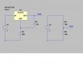
I have a regulated 5v source that I need to get 2v from to control an oscillator. My first thought was to make a voltage divider like on the right side of my attached diagram (ltspice). I never was comfortable with this since about 8ma goes through R4 for no purpose. So I thought to use a voltage regulator, like an LM317. That's on the left side of the diagram. That gets the two volts and only 1ma goes wasted through R2. I have a couple questions.
1) on the right, if there is some path with resistance from Vout to ground won't that mess up the voltage divider and change the 2v?
2) on the left, there are lots of combinations of R1/R2 that will get 2v output. I chose one with a large R2 value to lessen wasted current, are there other reasons to choose these resistors?
3) on the left is the 2v going to be more steady because there is no effect like I wondered about above?
Thanks, Jim
Attachments
-
 28.6 KB Views: 40
")


