Need help with tl072

Thread Starter

ad8chd

Joined Apr 28, 2023
17
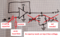
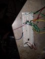
This is my first post on the forum, if I make any social errors please roast me so I don't do it again... Anyway I'm trying to build a guitar pedal (up until 2 months ago I knew literally nothing about electricity) but I have a m5223al op-amp that I have sounding pretty good, but I'm trying to use a tl072 as a buffer before the other circuit. I have a few I pulled out of other stuff but I can't seem to get it right, I built the unity gain circuit from the datasheet with the only substitution being a 2.2k resistor in place of a 2 k, and my signal is slightly more quiet. Also when I run it in front of the other circuit I can hear music from a headphone jack make it all the way through but not from my guitar. It's hard to use the probe while playing so I haven't been able to really trace it down. Also if anyone knows how to bias a transistor and isn't trying to keep it a secret like the rest of the internet I'd love to hear your thoughts on that as well. Thanks in advance. This is my breadboard, don't know if that helps
 

Attachments

MrChips

Joined Oct 2, 2009
30,795
Welcome to AAC!

Basic or advanced electronics is not something you learn overnight or over a weekend. Consider that just learning the basics takes 3-4 years of college or university training, followed by another 2-5 years of apprenticeship work. But don't give up just yet. Stick around and you might pick up some tips of the trade.

You actually have two separate questions. So let's take one at a time.

1) Breadboarding a circuit on solderless breadboards is just for proof of concept. Don't expect stellar performance from a breadboard circuit. For one thing, all those long wires become perfect radio antennas, broadcasting and receiving signals that you don't want to hear. For quality performance you need to go to a printed circuit board with special attention paid to component and trace layout, or at least reduce you circuit and wiring down to a minimum size on perfboard.

What they don't tell you in many courses, schools, and internet sites is that there are some essential components missing in your circuit, in particular, proper power supply decoupling capacitors. As I said, stick around 'cause there is so much more to learn.

2) How to bias a transistor?
This is not a question that can be answered in one thread. This is no tightly held secret. It is all there readily available on the internet but don't be surprised if it takes a complete textbook in order to cover all the fine details. So I will not waste your time and mine trying to do so here. There is a place and time for this. I believe that you are not quite prepared for this at this point. Let's get through some other basics first.

So, stick around and enjoy the show while you can!
 

Thread Starter

ad8chd

Joined Apr 28, 2023
17
Welcome to AAC!

Basic or advanced electronics is not something you learn overnight or over a weekend. Consider that just learning the basics takes 3-4 years of college or university training, followed by another 2-5 years of apprenticeship work. But don't give up just yet. Stick around and you might pick up some tips of the trade.

You actually have two separate questions. So let's take one at a time.

1) Breadboarding a circuit on solderless breadboards is just for proof of concept. Don't expect stellar performance from a breadboard circuit. For one thing, all those long wires become perfect radio antennas, broadcasting and receiving signals that you don't want to hear. For quality performance you need to go to a printed circuit board with special attention paid to component and trace layout, or at least reduce you circuit and wiring down to a minimum size on perfboard.

What they don't tell you in many courses, schools, and internet sites is that there are some essential components missing in your circuit, in particular, proper power supply decoupling capacitors. As I said, stick around 'cause there is so much more to learn.

2) How to bias a transistor?
This is not a question that can be answered in one thread. This is no tightly held secret. It is all there readily available on the internet but don't be surprised if it takes a complete textbook in order to cover all the fine details. So I will not waste your time and mine trying to do so here. There is a place and time for this. I believe that you are not quite prepared for this at this point. Let's get through some other basics first.

So, stick around and enjoy the show while you can!
you're not wrong, ele tricity is hard. I just wanted to make some cool stuff for my guitar and my old nemesis math shows up... So my original circuit is properly decoupled, and giving my pretty much the frequency response I'm looking for, but my guitar with the really high impedance pickups feels a little spongy, hence the need for the buffer. It is soldered to perfboard as well (actually to another board I cannabalized and sanded off all the conductive material) that op-amp didn't give me much of a fight to get working. This one though... And for the transistors I just don't really know where I get started. I have and understand most of the formulas, just having a hard time with where I get the first set of numbers to work out the rest. I've pulled it off A few times with pots in place of r sistors but it was sheer luck lol But I'm having a good time playing with my wires for now so I will definitely stick around.
Do you know of a good place for e to try looking for material that might help me figure out this stuff?
 

Ian0

Joined Aug 7, 2020
9,803
You should be able to get a unity-gain buffer working without any maths!
Something will be connected wrong. Perhaps there is no DC path to ground on the input. Circuit diagram will help.
 

Audioguru again

Joined Oct 21, 2019
6,688
The very old original dual opamp is like a copy of an LM358. It is noisy, produces crossover distortion and has trouble at high levels above 5kHz.
The TL072 has very high Jfet input resistance, low noise, very low distortion and works well up to 100kHz.

We cannot help you until you post the schematic of the circuit you are making.
 

Thread Starter

ad8chd

Joined Apr 28, 2023
17
The very old original dual opamp is like a copy of an LM358. It is noisy, produces crossover distortion and has trouble at high levels above 5kHz.
The TL072 has very high Jfet input resistance, low noise, very low distortion and works well up to 100kHz.

We cannot help you until you post the schematic of the circuit you are making.
The funny thing is the older op-amp gave me very little fuss. I'll post a schematic as soon as I get home, thanks.
 

MrChips

Joined Oct 2, 2009
30,795
The only math you need for most problems in electronics is knowing how to apply Ohm's Law.
We don't know the level of electronics knowledge and experience you have.
Here are three simple exercises for you that will help us gauge your electronics knowledge.

1) Calculate the current flowing in each resistor and the voltage across each resistor.
What is the power dissipated by each resistor?
Ex2 - series-parallel circuit.jpg


2) What is the voltage reading of the digital multi-meter?
Ex2 - voltage divider with DMM.jpg

3) What is the current flowing in diode D1 and D2? What is the voltage across resistor R1 and R2?Ex3 - diode.jpg
 

Thread Starter

ad8chd

Joined Apr 28, 2023
17
Ok so here is what I've got, the one with all the stuff is the m5223al and sounds pretty good, the smaller one is what's giving me issues. I would like to use the tl072 as a buffer because of it's high input impedance since guitar pickups don't really make a huge amount of signal. And actually, what I'd really like is to use like 3 or 4 of them in a row to try to get a more organic, over drive type of distortion rather than relying on the clipping diodes, but I figure I should learn to get one working first...16827960820678519068109370463282.jpg16827961256525275444002985132065.jpg16827961256525275444002985132065.jpg
 

Thread Starter

ad8chd

Joined Apr 28, 2023
17
The only math you need for most problems in electronics is knowing how to apply Ohm's Law.
We don't know the level of electronics knowledge and experience you have.
Here are three simple exercises for you that will help us gauge your electronics knowledge.

1) Calculate the current flowing in each resistor and the voltage across each resistor.
What is the power dissipated by each resistor?
View attachment 293121


2) What is the voltage reading of the digital multi-meter?
View attachment 293122

3) What is the current flowing in diode D1 and D2? What is the voltage across resistor R1 and R2?View attachment 293123
I don't know anything about electricity, a couple months ago my amp crapped out and I was playing with all the parts and came across a website with a whole community of people who build guitar effect pedals and thought it would be cool to try. I've just been finding data sheets for all the parts, trying to copy circuits and changing the value of components and ordering things differently to learn what everything does. I can do basic algebra and that's about it. I do know ohms law but I don't really understand how to apply it,


The only math you need for most problems in electronics is knowing how to apply Ohm's Law.
We don't know the level of electronics knowledge and experience you have.
Here are three simple exercises for you that will help us gauge your electronics knowledge.

1) Calculate the current flowing in each resistor and the voltage across each resistor.
What is the power dissipated by each resistor?
View attachment 293121


2) What is the voltage reading of the digital multi-meter?
View attachment 293122

3) What is the current flowing in diode D1 and D2? What is the voltage across resistor R1 and R2?View attachment 293123
I don't know anything about electricity, a couple months ago my amp crapped out and I was playing with all the parts and came across a website with a whole community of people who build guitar effect pedals and thought it would be cool to try. I've just been finding data sheets for all the parts, trying to copy circuits and changing the value of components and ordering things differently to learn what everything does. I can do basic algebra and that's about it. I do know ohms law but I don't really understand how to apply it, for that first problem my uneducated guess is r1 and r2 having 6 amps each and r3 at 1.5, for voltage I'm a little confused because I want to say

The only math you need for most problems in electronics is knowing how to apply Ohm's Law.
We don't know the level of electronics knowledge and experience you have.
Here are three simple exercises for you that will help us gauge your electronics knowledge.

1) Calculate the current flowing in each resistor and the voltage across each resistor.
What is the power dissipated by each resistor?
View attachment 293121


2) What is the voltage reading of the digital multi-meter?
View attachment 293122

3) What is the current flowing in diode D1 and D2? What is the voltage across resistor R1 and R2?View attachment 293123
I don't know anything about electricity, a couple months ago my amp crapped out and I was playing with all the parts and came across a website with a whole community of people who build guitar effect pedals and thought it would be cool to try. I've just been finding data sheets for all the parts, trying to copy circuits and changing the value of components and ordering things differently to learn what everything does. I can do basic algebra and that's about it. I do know ohms law but I don't really understand how to apply it, for that first problem my uneducated guess is r1 and r2 having either 6 amps each or 3, and r3 at 1.5 or .75 for voltage I'm a little confused because I want to say either 6 or 12 for r1 and r2 but I really don't know. R1 and r2 are a voltage divider so r3 should be getting 6 volts I think? Like I said until 2 months ago all I knew about electricity was to use a short wrench to take off a car battery.
 

Ian0

Joined Aug 7, 2020
9,803
Where are you getting the 4.5V reference from?
Your first buffer and the 47k resistor before it aren't contributing anything useful - delete them.
 

MrChips

Joined Oct 2, 2009
30,795
If you want to build your own guitar pedals then you ought to become comfortable with at least some basics of electronics.
Knowing how to apply Ohm's Law is one essential starting point. If you want to pursue this approach, then tackling a simpler version of my first question might help.

Can you do this one?

Calculate the current in each resistor and the voltage across each resistor.
Ex1a - Ohms Law.jpg
 

Ian0

Joined Aug 7, 2020
9,803
The original designer did not know that a buffer opamp is not needed.
Your buffer opamp did not work because it was missing an important input bias voltage and coupling capacitor.
I agree about the buffer and the bias. I presume that the diodes are a distortion network and as they will conduct quite some current connecting them to the 4.5V bias will make a real mess of the 4.5V bias. They should go to earth as you point out.
Although it seems to be the defacto standard, 1MΩ is too high a load impedance for a guitar pickup. 220k works much better, because it doesn't produce a huge peak in the treble region cause by the resonance between the inductance of the pickup and the capacitance of the cable. (Obviously, the pitch of the resonance varies with the cable length)
 

Audioguru again

Joined Oct 21, 2019
6,688
I never listen to the extreme fuzz and buzz distortion from an electric geetar. I think the players and listeners are deafened to the high frequencies so they use a 1M input resistance on the amplifier then they hear the high frequencies caused by the peak.

My age (77) killed my hearing but it is normal for my age and for people deafened by listening to loud noise and loud electric geetars. Without my hearing aids I can barely hear the distortion and high frequency peak.
The amplifier input resistance and cable capacitance affects the peak like this:
 

Attachments

Thread Starter

ad8chd

Joined Apr 28, 2023
17
Where are you getting the 4.5V reference from?
Your first buffer and the 47k resistor before it aren't contributing anything useful - delete them.
4.5 volts is half of the 9 volt supply and I just put a couple matching resistors as a voltage divider. And that circuit is already built and soldered on a board, but if I ever figure out how to do the rest of what I want to do, when I reassemble and put in the cabinet I will get rid of them.
 

Ian0

Joined Aug 7, 2020
9,803
I never listen to the extreme fuzz and buzz distortion from an electric geetar. I think the players and listeners are deafened to the high frequencies so they use a 1M input resistance on the amplifier then they hear the high frequencies caused by the peak.

My age (77) killed my hearing but it is normal for my age and for people deafened by listening to loud noise and loud electric geetars. Without my hearing aids I can barely hear the distortion and high frequency peak.
The amplifier input resistance and cable capacitance affects the peak like this:
What confuses guitarists is when they play on a bigger stage, use a longer lead and get a completely different sound, because that treble peak is an octave lower. Then they think their amplifier has gone wrong.
 

Thread Starter

ad8chd

Joined Apr 28, 2023
17
If you want to build your own guitar pedals then you ought to become comfortable with at least some basics of electronics.
Knowing how to apply Ohm's Law is one essential starting point. If you want to pursue this approach, then tackling a simpler version of my first question might help.

Can you do this one?

Calculate the current in each resistor and the voltage across each resistor.
View attachment 293131
So maybe the current is r1=2.5 & r2=1.6666 because v\r =A ? I think there will be 3 volts between them but I'm shaky on going across each, maybe 5 across each? But that can't be right or else it wouldn't be a math problem cause it would be a trick question huh. So I've been trying to find info online but Google ain't really what it used to be, most sites are ai written ads and worthless. I would love to be pointed I. The direction of some study material I can read (I'd rather not watch videos) I would appreciate it, or if anyone is feeling super generous and in the mood to spoon feed this baby bird I wouldnt turn down the help but I completely respect making me do the work.
 

Thread Starter

ad8chd

Joined Apr 28, 2023
17
The original designer did not know that a buffer opamp is not needed.
Your buffer opamp did not work because it was missing an important input bias voltage and coupling capacitor.
EDIT: What resistors and capacitor make the +4.5V?
I've actually got the half Vcc going into the same pin as my signal, I didn't draw it because I was in a hurry and just drew it from the datasheet without thinking about the cap and the rest of it. On the original design (the IC came from a boss ds1 pedal) there is a jfet buffer that I would have much rather went with but transistors are giving me a really hard time. The circuit that does work (the op-amp section of the ds1) actually sounds pretty good, but I'd like to get all that distortion from a few stages a little at a time rather than all from one chip so I was going to try to run the buffer into another couple tl072's I have them into that then into a lm386. I was hoping by the time I got there I will have figured out how to hook it up to a transformer and have a little homemade amp. The voltage divider on the circuit that works is 2 1k resistors, the coupling cap is I think .47u. on the tl074 I've been trying all different values.
 
Top