Automatic selection from three 12v (DC) sources

Thread Starter

woytovich

Joined Feb 5, 2023
8
Context:
a camper van environment (24v stock electrical system)
12v DC loads need power (fed from a 12v fuse box)

Sources:
A. 120v >12v power supply
B. 24v alternator/main battery bank >12v converter
C. 12v "house" battery

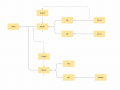
I would like to prioritize the source selection for the 12v going into the 12v fuse box.
Ideally this is automatic.

Priority:
In the order above: A, B then C:
Use (A) 120v power supply if it is powered up
else use (B) the alternator supplied power if the vehicle is running
else use (C) the 12v "house" battery

My head is spinning from the research I've been doing. (I'm a relative novice when it comes to DC electrics.)
Diodes, relays, charger controller...?

I'm not looking to cobble together a huge wiring project. If there is a device that'll do this that is not $$$$$ I'll be good with that. That said I'm not afraid to wire up some relays or even diodes if that is a "better" solution.

The attached diagram shows the "?????" that I am needing to solve.

Thanks folks.
 

Attachments

Reloadron

Joined Jan 15, 2015
7,523
Priority:
In the order above: A, B then C:
Use (A) 120v power supply if it is powered up
else use (B) the alternator supplied power if the vehicle is running
else use (C) the 12v "house" battery
You actually said how I would likely approach this. The keyword is not so much else but if. I would just use a simple uC (micro-controller) for the decision making. Just figure a way to provide some digital inputs. If 120 VAC available is True then do this. Else If Vehicle Running then do this. Else If ... you get the idea. Then use three digital outputs to switch your sources. You will want three contactors capable of handling the loads on your fuse panel. Can this be done using discrete components? Yes, the logic can be worked out but you need a small mountain of parts. Letting a uC do the "thinking" seems an easier approach. Chips like Arduino and PICAXE come to mind and again it's a matter of mapping out the logic. Things like what if all three conditions are true? What if two out of three are true? Once things are mapped out the programming shouldn't be that difficult. We have some really good programming types in this forum. Me? I dabble in it. :) Anyway I would go the uC route but there are other ways. The three contactors need to handle the load and some overhead and also "continuous duty" types.

Also look into a PLC (Programmable Logic Controller) to do the thinking. Once expensive they can be had inexpensive including a display.

Ron
 

WBahn

Joined Mar 31, 2012
30,076
One possibility to consider is to just connect all three together via appropriately rated diodes. Then the camper will draw from whichever one is at the highest voltage while preventing any one supply from driving either of the others. This assumes that the 12 V converter in the vehicle doesn't output anything if the engine isn't running, which is probably a pretty good assumption since it would otherwise drain the vehicle battery. Similarly, it assumes that there is no significant voltage appearing at the 12 V output of the 120 VAC inverter when it is either disconnected or turned off.

If the highest one happens to be the "wrong" one, this is not a situation that would continue for two long before the load would shift to another source.

Other solutions that use components to do the logic will have to contend with a similar issue -- which source do you use to power the devices that are being used to decide which power source to use to power them? The diode-OR'ed approach can at least be used for that purpose.

You can certainly use a microcontroller to implement the logic. You just have to be able to detect the state of power availability from each source (or at least the first two) and then be able to output a signal to activate a relay or isolator or contactor for the chosen source. But unless you use a latching relay, all of these will present a parasitic load that will eventually drain the house battery if the other two are not present for long enough. While a latching relay solves this problem, the logic will be a bit more complicated because you have to be able to disengage each relay before switching to another. So you might consider an additional Master Power switch that must be turned on manually in order for the camper to get any power from any source. This can also be used to prevent the diode-OR'ed power rail from presenting a parasitic drain (although another option is to use that rail to power anything that must have continuous power, like clocks or devices that lose their memory if disconnected even for a second or so).

Finally, how is the house battery recharged? If that is done by connecting both it and one of the other sources at the same time, you'll want an override switch for that.
 

MisterBill2

Joined Jan 23, 2018
18,584
REally, it can be very simple to have the equivalent of a static "OR" function. All it should require is three diodes able to handle the current that the loads will require. It might require adjusting the voltage from the 120 volt powered supply to be a bit above 13 volts, but that should not be an issue..
Consider the following logic:
If 120 volt AC is available, the 12 volt AC powered supply will be active and it's voltage will forward bias it's connecting diode. That supply voltage will be a bit greater than the battery voltage when it is not being charged, so the 120 volt supply will deliver power. If 120 is not available, then either the battery or the alternator will deliver power, no control logic required.
If the alternator is delivering charge, the vehicle engine must be running, and so the output voltage will be much closer to 14 volts, which is greater than the battery voltage, and so the alternator connection diode will be forward biased, selecting the alternator output.
If the engine is not running then the alternator output will be zero, and so the default will be the 12 volt house battery, which will forward bias the house battery connection diode.
There you have the fully automatic change-over system with no processor and no power consuming contactors or processor. No software required.

Probably there is a way to use mosfets to do the switching, with the advantage being much lower forward voltage drop, which will provide much better efficiency. and still no little processor driving power burning relays or contactors.
AND, by the way, this scheme is not original from me.
 

WBahn

Joined Mar 31, 2012
30,076
This is the diode-OR'ed connection I described. But if the 120 V-powered supply is set to just above 13 V and the alternator is delivering ~14 V when the engine is running, that alternator will be chosen over the 120 V-sourced supply, which is not what the TS wants. For this to work as desired, the 120 V-sourced supply must be slightly higher than the voltage coming from the alternator, which must in turn be higher than the house battery.
 

Thread Starter

woytovich

Joined Feb 5, 2023
8
As shown in the pic I posted the 12v battery will be getting charged when there is power from the 24>12v charger, or thru a 120>12v charger (not shown in the pic)
 

MisterBill2

Joined Jan 23, 2018
18,584
This is the diode-OR'ed connection I described. But if the 120 V-powered supply is set to just above 13 V and the alternator is delivering ~14 V when the engine is running, that alternator will be chosen over the 120 V-sourced supply, which is not what the TS wants. For this to work as desired, the 120 V-sourced supply must be slightly higher than the voltage coming from the alternator, which must in turn be higher than the house battery.
Certainly that is correct, BUT the presumption is that the alternator is only operating when the vehicle engine, mostly used to move the vehicle, is running. And usually the fixed point AC feed is not active when the vehicle is in motion. Possibly a very long extension cord would provide the exception. This may be another case of a TS not providing enough context information.
 

Thread Starter

woytovich

Joined Feb 5, 2023
8
"And usually the fixed point AC feed is not active when the vehicle is in motion"
Yes, sorry.... shore power(120v) would not normally be hooked up when the engine is running (although possible I suppose).
Ideally I'd want solid logic (as one might envision with manual switches or relays) rather than relying on actual supply voltages.
 

Thread Starter

woytovich

Joined Feb 5, 2023
8
I know about solar charge controllers and voltage sensing relays in dual battery systems but I have not found a device that will handle 3 incoming 12v sources in a selectable order of priority.
 

MisterBill2

Joined Jan 23, 2018
18,584
The diode logic scheme is rather solid. The only lack of efficiency is in the diode voltage drops.
But to effect a more definite chang-over when shore power is connected, a mains powered transfer contactor could be used. That would avoid any battery drain operating the one change over point. The alternator voltage is always greater than the battery voltage and so that change over is intrinsic, like in a car. The alternator diodes isolate the alternator when it is not operating..
 
Last edited:

WBahn

Joined Mar 31, 2012
30,076
Certainly that is correct, BUT the presumption is that the alternator is only operating when the vehicle engine, mostly used to move the vehicle, is running. And usually the fixed point AC feed is not active when the vehicle is in motion. Possibly a very long extension cord would provide the exception. This may be another case of a TS not providing enough context information.
No long extension cord needed; I can easily envision cases when all three might be available. The vehicle pulls into a parking location and leaves the engine running while external power is connected, possibly to top of the vehicle battery, or to allow the headlights to continue being used without draining the vehicle battery, or out of concern that the house battery might not be sufficiently charged to handle the transition load. Similarly, the vehicle might be started prior to leaving to warm up the engine and or cab while the camper remains on external power until shortly before departure.
 

WBahn

Joined Mar 31, 2012
30,076
I know about solar charge controllers and voltage sensing relays in dual battery systems but I have not found a device that will handle 3 incoming 12v sources in a selectable order of priority.
Cascade two of them. Use one to choose between your two non-house sources and then the other to choose between the house battery and the output of the first.
 

Thread Starter

woytovich

Joined Feb 5, 2023
8
Cascade two of them. Use one to choose between your two non-house sources and then the other to choose between the house battery and the output of the first.
I need a visual... I get it generally but...
(Thanks for your patience with my ignorance)
 

Thread Starter

woytovich

Joined Feb 5, 2023
8
I'm a very visual/mechanical guy. I know that's not always ideal. In any case this is what I'm envisioning with a relay solution. This assumes NO/NC relays can have their load current run "backwards (IN through the NO/NC pin and OUT through what would normally be the supply current. (is that all wrong?)
I'm thinking I STILL might need diodes to stop current from flowing back into the "off" parts of the system?
 

Attachments

bassbindevil

Joined Jan 23, 2014
828
I'm not sure that diodes or relays are necessary. If you have a 24 to 12V charger that only operates when the engine runs, that will top up the house battery and supply any 12V loads with current. And a 120VAC to 12V charger will do the same when running on "shore power". Take a look at boxes from Renogy; they have things for RVs and off-grid.
 
Top