Thermal Protection System

Thread Starter

Sensacell

Joined Jun 19, 2012
3,420
I am working up a design for a thermal protection system for some LED lighting.

The lights are RGBW DMX controlled lights, when all 4 colors are on full, the thing overheats, but normally all 4 channels are never turned on. The dimmers are off-the-shelf so I cannot modify them.
An open circuit DMX input picks up stray voltages which can be easily interpreted as an "everything on full" signal, so I need to implement a hardware solution.


There are three LED boards, so the idea is to have 3 small 2-wire sensor boards connected to a common bus (wired OR) that nominally draw 200uA, but when the temp goes over 60 degrees C, they draw 10 mA, which then shuts down the LED common supply via some yet-to-be-designed circuit

The sensor should have 5 degrees of hysterisis to prevent the thing from flashing all crazy around the trip point.

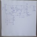
Attached is a rough sketch of an idea, based on an analog temp sensor and a TL431 as a reference and comparator.

The PNP is supposed to provide 100 mV of hysteresis, but I think it needs to be a PFET not a bipolar.

The whole thing runs on 24 VDC about 2A max.

Any ideas how this could be simpler?
 

Attachments

PaulEE

Joined Dec 23, 2011
474
Let's simplify to understand the bare bones problem here if we could.

You have a load that you want to shut off when the temperature breaches a set-point.

Is that correct?

Paul
KI5VNH
 

Thread Starter

Sensacell

Joined Jun 19, 2012
3,420
Let's simplify to understand the bare bones problem here if we could.

You have a load that you want to shut off when the temperature breaches a set-point.

Is that correct?

Paul
KI5VNH
That is correct- over 60 degrees C = shutdown, then self reset at 55 C. But the load is actually 3 separate units, all of which need sensing.
 

PaulEE

Joined Dec 23, 2011
474
So basically, you would like advice on designing a thermostat.

Is that an accurate representation of the problem?

Paul
KI5VNH
 

PaulEE

Joined Dec 23, 2011
474
You already have the hard part, quite honestly...the little temperature sensor is quite handy.

Here is what I'm thinking:
-Need to sense temp and convert it into an electrical quantity: your sensor is perfect for this task, and probably reasonably accurate
-The sensor has voltages for all the temperatures you need to know about, and you are 100% correct about wanting some hysteresis

So, we need a circuit that, when it sees anything above 60C, it should turn OFF the LEDs, and not turn back ON until it hits 55C.

What we just described there is a comparator. The TL431 is a perfect candidate for a voltage reference with which we can compare the temperature sensor output with.

Hysteresis is added to a comparator with properly-chosen feedback resistors.

At that point, you can drive a transistor to turn a relay on or off.

I would personally hook the LEDs up to the normally-CLOSED side of the relay, and use your circuit to energize the relay when the temperature hits the trip-point, so that energizing the relay turns the LEDs OFF. Otherwise, the relay will sit there ON and waste power when the LEDs aren't 60C.

What do you think of that idea?

I can help you work through that design if you'd like.

Paul
KI5VNH
 

Thread Starter

Sensacell

Joined Jun 19, 2012
3,420
Here is my idea for the switch part of the circuit.

Q1 and the TL431 form a 5V regulator. Q4 forms a current sink that keeps about 10V on R9, which keeps the PFET Q5 solidly ON. Q3 shunts the base voltage at Q4 to ground when Q2 turns on, which happens when more than about 5 mA flows in R2. R3 provides short-circuit protection.

Three of the sensor circuits are powered by this circuit, so any one of them can trigger a shutdown.

Thoughts?
 

Attachments

MisterBill2

Joined Jan 23, 2018
18,061
" The Thing Overheats" leaves a lot of information missing. My guess is that the power source is what over heats if all four are dimmers are set towards maximum brightness, which increases the total supply current. So the very simple fix will be to either switch off if the current exceeds some limit value, or reduce the supply voltage to limit the total power as the current exceeds that set limit.
Overheating is the result that is to be prevented, and only happens after the excess power has been used for some time.
So a single current sensing resistor in the main power circuit can allow a single comparator circuit to either switch off the power completely or just change the voltage set-point to a lower level. No changes to any of the dimmer circuits, nor the addition of any temperature monitoring components.
The trick was understanding the source of the problem rather than the symptom.
 

PaulEE

Joined Dec 23, 2011
474
MisterBill2, good thoughts. My impression was that he had these relatively high power LEDs in an enclosure, and that was what was overheating. But yes, I agree that perhaps more info is needed.

It sounded like he wanted to place a temp sensor and associates circuitry within (at least the temp sensor anyway) the enclosure and shut the power off to any one LED “can” if temps got too high.

What it also seems like is that he is dying to use transistors to solve this problem…I like transistors too, but if making a thermostat is what he after, you and I both know that’s typically done in analog with a comparator or op-amp.

So, I am left a bit confused at this point.

Paul
KI5VNH
 

Thread Starter

Sensacell

Joined Jun 19, 2012
3,420
The light fixture has 4 color channels, RGBW.
The design goal is to have high light output from a very slender form factor, so it naturally has high thermal resistance.

Normally we never use more than one color on full power, with maybe 50% of another (color mixing, 35% of max system power) so we can get away with not much of a heat sink.

Momentary power excursions up to 100% power are also required, just limiting the instantaneous input power is not an option, it needs to sense the actual light engine PCB temperature.

The temp sensing circuit will be built into each LED PCB, it needs to be small, cheap and layout-flexible so it can be placed into a tight array of SMD LED packages on a slender board.

My design for the "sender" part of the system requires only 3 SOT-23-3 parts and a few resistors, it seems pretty minimal and layout-friendly?

Others have mentioned my love of discrete transistors, can anyone suggest a better, cheaper, smaller design concept?

It also occurs to me that I could "trim" the setpoint temp a little by adjusting the 5V rail up or down a little, by changing just one resistor.

The TL431 accomplishes the accurate voltage reference and comparator function in a single tiny part, can I do better?

We need to produce about 400 of these fixtures.
 

PaulEE

Joined Dec 23, 2011
474
The little sender circuit on each PCB…does this little board send the main power box a signal to either turn on or off power? In other words, high/low from temp circuit to control power source? Or must the power switch also be on the little temp board?

I do have a thought but want to clarify first…

Paul
KI5VNH
 

Thread Starter

Sensacell

Joined Jun 19, 2012
3,420
The little sender circuit on each PCB…does this little board send the main power box a signal to either turn on or off power? In other words, high/low from temp circuit to control power source? Or must the power switch also be on the little temp board?

I do have a thought but want to clarify first…

Paul
KI5VNH
With my notes here I am attempting to describe the preliminary design idea that I have posted as part of this thread. (See images attached to my previous posts, post #6 shows the switch portion) I have not prototyped or simulated the circuits yet. My goal here is to arrive at an optimal solution by inviting others to critique my design ideas.

My process usually involves working up a few solutions without going too deep, then showing them to some smart people for feedback.
Then I go back and finalize the solution with the new perspective I gain from discussing it with others.
 
Last edited:

Thread Starter

Sensacell

Joined Jun 19, 2012
3,420
So - as for what I just asked - does that mean you aren't sure yet what the plan is?

Paul
KI5VNH
Lacking some new revelations, the plan is to prototype the circuit(s) as designed and see if they actually work the way I believe they should.

One assumption I am making is that the microchip temperature sensor output can sink 200uA and still output the correct voltage, I assume the output stage can both source and sink small currents, the data sheet did not help me to sort this out.
 

MisterBill2

Joined Jan 23, 2018
18,061
It can also be done using thermistors to sense the temperature, or even a few small, low current, silicon diodes in series to sense the temperature, since the forward voltage drop across a silicon diode increases with temperature. Then either a transistor stage of amplification or an IC comparator to sense that the voltage drop, and thus the temperature, has exceeded some limit value. Small silicon diodes are about as small a component as is cheaply available. And they could be mounted on the same circuit board as the LEDs, providing good temperature transfer to the sensors.
But since the current will also provide a very direct indication of the power fed into the assembly, it will also provide information about the temperature even before the overheating happens.
 

PaulEE

Joined Dec 23, 2011
474
MisterBill2, certainly a cheap way to do it...in fact, that MCP9701 device effectively does what you suggest, except that it is mass-produced and probably more repeatable part-to-part. One 8-bit micro with a thermometer in it would solve this entire thing; too bad they aren't available, and would probably stop working before it could do its job :)
Sensacell,

Going back to your first post - I apologize, I completely forgot about the innerds of the TL431; it basically is what I'd suggested a post or two ago, and that was exactly what you were doing. Face-palm on that one (for myself)!

To answer your question on the MCP9701, 0.4V out at 0*C and 19.5mV/*C...it looks like a fairly low output current signal; I would not source or sink much from this...however...

I believe what you wanted to do in the first place is to use the output of the TL431 (as in, the output transistor, if you look at its equivalent circuit) as a switch in such a way as to adjust the threshold of turn on (/off) of itself, given the temperature sensor as an input.

So you effectively had this:
1672603331477.png

I have not exhaustively analyzed what's going on here, but the general idea is a good one, and I think you're on the right track with this.

If you would like me to use this technique and run some numbers "as if it were me designing the circuit", I'm happy to do so.

But as far as accomplishing the goal, you're definitely employing MisterBill2's temperature-sensing suggestions with the MCP9701, and definitely adjusting the threshold with the comparator and reference of the TL431.

As far as repeatability and overall accuracy, I think this is rather hard to beat. Just be careful of the TL431, the voltage reference does have a temperature coefficient itself, and that will drift, causing some drift in your threshold.

You still would need the hi/lo output signal for your main power switch from this little circuit, though, but should be simple to get by picking one of the signals and buffering...

Price-wise... $0.22/MCP9701 in 100s and the TL431 is comparable...as far as price and accuracy...you're pretty close to the limit here, I would imagine.

Paul
KI5VNH
 
Last edited:

Thread Starter

Sensacell

Joined Jun 19, 2012
3,420
Thank you all for your input on this project.

I will breadboard this system with a few big SMD resistors as a heater/load to simulate the actual LED board.

Will report back with my findings.
 
Top