
Hi,
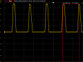
I am doing a side project that essentially tells the user what their heart rate is on a 16x2 LCD display. I am currently feeding my heart rate signal (going from 0 to ~4.6V on spikes) into the RB0/INT pin of the PIC16F877A. I am trying to use the capture mode of the PIC to tell me the time from one spike to the next. This is my first time using the Capture mode which is why I am trying to learn it well on this adventure.
Essentially, I want my program to detect a rising edge on this pulse waveform and to tell me the period. I am trying to count the number of rising edges and calculate the period based off that and the time elapsed between each one. Ultimately my goal is to find the average period of this pulse over a span of 15 seconds and then just multiply that by 4.
Currently, I believe my issue is that the PIC16F877A is either not detecting the rising edges, or that the ISR never activates. Any help would be appreciated, please let me know!
Attached is the oscilloscope of the pulse signal I am feeding the PIC and my code.
Mod edit: code tags - JohnInTX
I am doing a side project that essentially tells the user what their heart rate is on a 16x2 LCD display. I am currently feeding my heart rate signal (going from 0 to ~4.6V on spikes) into the RB0/INT pin of the PIC16F877A. I am trying to use the capture mode of the PIC to tell me the time from one spike to the next. This is my first time using the Capture mode which is why I am trying to learn it well on this adventure.
Essentially, I want my program to detect a rising edge on this pulse waveform and to tell me the period. I am trying to count the number of rising edges and calculate the period based off that and the time elapsed between each one. Ultimately my goal is to find the average period of this pulse over a span of 15 seconds and then just multiply that by 4.
Currently, I believe my issue is that the PIC16F877A is either not detecting the rising edges, or that the ISR never activates. Any help would be appreciated, please let me know!
Attached is the oscilloscope of the pulse signal I am feeding the PIC and my code.
C:
-------------------------------------------------------------------------------------------------------------------------------------------------

#define _XTAL_FREQ 20000000

#define RS RD2
#define EN RD3
#define D4 RD4
#define D5 RD5
#define D6 RD6
#define D7 RD7

#include <xc.h>
#include <stdlib.h>
#include <stdio.h>
#include <stdint.h>
#include <string.h>

#pragma config FOSC = XT        // Oscillator Selection bits (XT oscillator)
#pragma config WDTE = OFF       // Watchdog Timer Enable bit (WDT disabled)
#pragma config PWRTE = ON       // Power-up Timer Enable bit (PWRT enabled)
#pragma config BOREN = ON       // Brown-out Reset Enable bit (BOR enabled)
#pragma config LVP = OFF        // Low-Voltage (Single-Supply) In-Circuit Serial Programming Enable bit (RB3 is digital I/O, HV on MCLR must be used for programming)
#pragma config CPD = OFF        // Data EEPROM Memory Code Protection bit (Data EEPROM code protection off)
#pragma config WRT = OFF        // Flash Program Memory Write Enable bits (Write protection off; all program memory may be written to by EECON control)
#pragma config CP = OFF         // Flash Program Memory Code Protection bit (Code protection off)

int count_ovf = 0;              //store timer1 ovf number
int numerator = 0;
char display[7];
int pulse = 0;
unsigned int tmr1_reg;   //store timer1 register value
unsigned long counter = 0;      //counter value
char counter_text[11];          //counter value converted to string
uint32_t period;                   //Stores periodic time
char period_text[20];           //Periodic time converted to string
char freq_text[20];
uint32_t frequency;

//From site test
unsigned short pulse_count;
unsigned short pulse_rate;

unsigned short edge_counter = 0;    //determine first and second rising edges of the pulse
__bit flag;                       //Will be set if 2 edges are detected so freq and period can be calculated

void Lcd_SetBit(char data_bit) //Based on the Hex value Set the Bits of the Data Lines
{
    if(data_bit& 1)
        D4 = 1;
    else
        D4 = 0;

    if(data_bit& 2)
        D5 = 1;
    else
        D5 = 0;

    if(data_bit& 4)
        D6 = 1;
    else
        D6 = 0;

    if(data_bit& 8)
        D7 = 1;
    else
        D7 = 0;
}

void Lcd_Cmd(char a)
{
    RS = 0;
    Lcd_SetBit(a); //Incoming Hex value
    EN  = 1;
    __delay_ms(4);
    EN  = 0;
}

Lcd_Clear()
{
    Lcd_Cmd(0); //Clear the LCD
    Lcd_Cmd(1); //Move the curser to first position
}

void Lcd_Set_Cursor(char a, char b)
{
    char temp,z,y;
    if(a== 1)
    {
      temp = 0x80 + b - 1; //80H is used to move the curser
        z = temp>>4; //Lower 8-bits
        y = temp & 0x0F; //Upper 8-bits
        Lcd_Cmd(z); //Set Row
        Lcd_Cmd(y); //Set Column
    }
    else if(a== 2)
    {
        temp = 0xC0 + b - 1;
        z = temp>>4; //Lower 8-bits
        y = temp & 0x0F; //Upper 8-bits
        Lcd_Cmd(z); //Set Row
        Lcd_Cmd(y); //Set Column
    }
}

void Lcd_Start()
{
  Lcd_SetBit(0x00);
  for(int i=1065244; i<=0; i--)  NOP();
  Lcd_Cmd(0x03);
    __delay_ms(5);
  Lcd_Cmd(0x03);
    __delay_ms(11);
  Lcd_Cmd(0x03);
  Lcd_Cmd(0x02); //02H is used for Return home -> Clears the RAM and initializes the LCD
  Lcd_Cmd(0x02); //02H is used for Return home -> Clears the RAM and initializes the LCD
  Lcd_Cmd(0x08); //Select Row 1
  Lcd_Cmd(0x00); //Clear Row 1 Display
  Lcd_Cmd(0x0C); //Select Row 2
  Lcd_Cmd(0x00); //Clear Row 2 Display
  Lcd_Cmd(0x06);
}

void Lcd_Print_Char(char data)  //Send 8-bits through 4-bit mode
{
   char Lower_Nibble,Upper_Nibble;
   Lower_Nibble = data&0x0F;
   Upper_Nibble = data&0xF0;
   RS = 1;             // => RS = 1
   Lcd_SetBit(Upper_Nibble>>4);             //Send upper half by shifting by 4
   EN = 1;
   for(int i=2130483; i<=0; i--)  NOP();
   EN = 0;
   Lcd_SetBit(Lower_Nibble); //Send Lower half
   EN = 1;
   for(int i=2130483; i<=0; i--)  NOP();
   EN = 0;
}

void Lcd_Print_String(char *a)
{
    int i;
    for(i=0;a[I]!='\0';i++)[/I]
       Lcd_Print_Char(a);  //Split the string using pointers and call the Char function
}

void capture_init(){
    TRISBbits.TRISB0 = 1;           //Sets RB0 as input
    OPTION_REGbits.INTEDG = 1;      //Interrupt on rising edge of RB0/INT pin
    INTCONbits.INTE = 1;            //Enables INT0 external interrupt

  //Timer1 configs------------------------------------------------------------------
    //prescaler 1:8
    T1CONbits.T1CKPS1 = 1;
    T1CONbits.T1CKPS0 = 1;

    PIE1bits.TMR1IE = 1;            //Enable Timer1 ovf interrupt
    T1CONbits.TMR1ON = 0;           //Stops Timer1 at the beginning
    TMR1H = 0;                      //Reset high byte of TMR1
    TMR1L = 0;                      //Reset low byte of TMR1
  //--------------------------------------------------------------------------------

    //Enable all interrupts
    INTCONbits.PEIE = 1;        //Enable peripheral interrupts
    INTCONbits.GIE = 1;         //Enables global interrupts
}

void get_print_TMR1(){
    tmr1_reg = (TMR1H << 8) + TMR1L;        //get high and low bytes of TMR1

    //counter value calculation
    counter = (count_ovf* 65536) + tmr1_reg;

    //period calculation
    period = (counter + 1);
    period = period * 4;
    period = period * 1/20000000;
    period = period * 8;
    frequency = 1/period;

    //Convert period and counter values to a string
    sprintf(counter_text, "%d", counter);
    sprintf(period_text, "%d", period);
    sprintf(freq_text, '%d', frequency);

    //display TMR1 and period values
    Lcd_Set_Cursor(1,1);
    Lcd_Print_String("HEART RATE:");
    Lcd_Set_Cursor(2,1);
    Lcd_Print_String(freq_text);
    __delay_ms(200);

    //Reset Timer and counters
    TMR1H = 0;
    TMR1L = 0;
    count_ovf = 0;
}

//Timer_init() commented out right now
/*
//INITIALIZE timer. Use external interrupt (my wave) at rising edge and timer to measure period.
void timer_init(){
    INTCONbits.GIE = 1;         //Enables global interrupts
    INTCONbits.PEIE = 1;        //Enable peripheral interrupts
    INTCONbits.TMR0IE = 1;      //Enable timer interrupt
    INTCONbits.TMR0IF = 0;      //Clear timer overflow flag
    //************MIGHT WANNA DO THIS IN THE INTERRUPT***********
    ei();                       //Enable/unmask all interrupts (affects GIE bit)

    //Configure timer
    //Use option_reg for selecting clock source and prescalar
    OPTION_REGbits.T0CS = 0;        //Internal instruction cycle clock
    OPTION_REGbits.INTEDG = 1;      //Interrupt on rising edge of RB0/INT pin
    //OPTION_REGbits.PSA = 0;       //Prescaler assigned to Timer0 module

    //Select prescaler value 1:128 for TMR0
    OPTION_REGbits.PS0 = 0;
    OPTION_REGbits.PS1 = 1;
    OPTION_REGbits.PS2 = 1;

}*/

int main()
{
    unsigned int a;
    TRISD = 0x00;
    Lcd_Start();
    Lcd_Clear();

    //timer_init();
    capture_init();

    Lcd_Set_Cursor(1,1);
    Lcd_Print_String("HEART RATE:");
    Lcd_Set_Cursor(2,1);
    Lcd_Print_String("GOOD");
    __delay_ms(200);

    while(1)
    {
        if (flag == 1){
            get_print_TMR1();

            edge_counter = 0;
            flag = 0;
            //reenable all interrupts
            INTCONbits.PEIE = 1;        //Enable peripheral interrupts
            INTCONbits.GIE = 1;         //Enables global interrupts
        }
    }
    return 0;
}

void __interrupt() ISR()
{
    if(PIR1bits.TMR1IF == 1){           //Check for interrupt OVF bit (When timer overflows, it'll be set to 1)
        PIR1bits.TMR1IF == 0;           //Clear interrupt flag
        count_ovf++;                    //Increment every timer1 ovf
    }

    if(INTCONbits.INTF = 1){            //If INT0 interrupt occurs (rising edge detected)
        INTCONbits.INTF = 0;            //Reset INT0 int flag
        T1CONbits.TMR1ON = 0;           //Stop timer1

        edge_counter++;

        if(edge_counter == 1){          //First rising edge detected
            T1CONbits.TMR1ON = 1;       //TMR1 start counting
        }

        if (edge_counter == 2){          //Second rising edge detected
            //disable all interrupts
            INTCONbits.PEIE = 0;
            INTCONbits.GIE = 0;
            T1CONbits.TMR1ON = 0;        //Stop TMR1
            flag = 1;                    //Set this flag to indicate that the time of the pulse is counted
        }
    }

    /*
        //at Fout = 15 Hz, Fclk = 4 MHz, prescaler = 128, TMR0IF ovfs 2x in 15 sec
    if(count_ovf == 2){
        count_ovf = 0;
        PORTA =~ PORTA;

        Lcd_Clear();
        Lcd_Set_Cursor(1,1);
        Lcd_Print_String("HEART RATE:");
        Lcd_Set_Cursor(2,1);
        numerator = TMR0;

        numerator = numerator * 5;
        sprintf(display, "%d", numerator);
        Lcd_Print_String(numerator);
        __delay_ms(200);
    }*/
}Attachments
-
 739.2 KB Views: 2
Last edited by a moderator:


