
Hello All,
I am developing a very small I2C controlled Motor Driver PCB Board for a robot for my master's thesis.
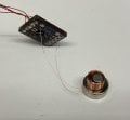
The idea is simple: Use ATTINY816 to send two PWM signals to the DRV8872 Motor driver to actuate an electromagnetic coil back and forth between two magnets. The PWM signals switch polarity at a rate of about 10 Hz.
Specs:
This is one small board that is daisy-chained with identical circuits to make a chain of I2C controlled motor drivers.
I have the I2C working perfectly, but it seems the motor driver is limiting the current being supplied to the coil.
With 7V going through a 30ohm coil, the current shouldn't exceed 233mA, and I have experimented with this to confirm.
Troubleshooting:
I tried substituting a resistor for the coil, and the driver would not supply current to a 30ohm resistor, but would work with a 47ohm resistor.
I then tried putting a 20ohm resistor in series with the coil to get ~50ohms resistance, but it would still not work.
Could there be something generating as spike that triggers the fault detection in the DRV8872?
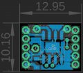
This is the first PCB I've ever designed, so any advice is welcomed in that design department, or even ways that you would troubleshoot this problem as I am a mechanical engineering grad student and still learning.
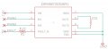
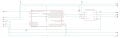
Attached are the schematics and PCB layer images.
(The schematic with just the motor driver is to help illustrate how the coil is connected to the circuit, there is only 1 coil connected to each PCB between the points Coil_1 and Coil_2)
I am developing a very small I2C controlled Motor Driver PCB Board for a robot for my master's thesis.
The idea is simple: Use ATTINY816 to send two PWM signals to the DRV8872 Motor driver to actuate an electromagnetic coil back and forth between two magnets. The PWM signals switch polarity at a rate of about 10 Hz.
Specs:
- ATTINY816 MCU
- DRV8872 Motor Driver
- Supply voltage for Driver: 7.0V
- Coil: 30 ohm (42AWG) air-core
This is one small board that is daisy-chained with identical circuits to make a chain of I2C controlled motor drivers.
I have the I2C working perfectly, but it seems the motor driver is limiting the current being supplied to the coil.
With 7V going through a 30ohm coil, the current shouldn't exceed 233mA, and I have experimented with this to confirm.
Troubleshooting:
I tried substituting a resistor for the coil, and the driver would not supply current to a 30ohm resistor, but would work with a 47ohm resistor.
I then tried putting a 20ohm resistor in series with the coil to get ~50ohms resistance, but it would still not work.
Could there be something generating as spike that triggers the fault detection in the DRV8872?
This is the first PCB I've ever designed, so any advice is welcomed in that design department, or even ways that you would troubleshoot this problem as I am a mechanical engineering grad student and still learning.
Attached are the schematics and PCB layer images.
(The schematic with just the motor driver is to help illustrate how the coil is connected to the circuit, there is only 1 coil connected to each PCB between the points Coil_1 and Coil_2)
Attachments
-
 123.6 KB Views: 15
 -
 52 KB Views: 16
 -
 53 KB Views: 18
 -
 118.1 KB Views: 21
 -
 72.3 KB Views: 20


