Hey Folks,
I've recently got a Bose L1 compact sound system in for repair. The unit failed to power up one fine day.
After opening the unit up the first thing I noticed was the TOP258 IC was cracked open. Before replacing the IC I had a look for any other components which might have failed. I checked for the obvious culprits and I couldn't find anything which has failed. I checked the diodes and resistors around the IC, checked the main filter caps and the electrolytics near the IC. Checked the secondary side for any shorts or failed caps and nothing . I checked the capacitors with the ESR meter, I removed some capacitors and checked them with my multimeter for the capacitance value as well.
So after much contemplation, I decided to change the IC only but the thing was I couldn't get hold of any TOP258 ICs. So I placed order for those. However I had TOP256 IC in my parts bin. It can handle low power than the 258 and to see if anything else failed I replaced it with it (until I got the 258). Powered it up and it was working. Obviously I didn't run it at full volume or had it on for long.
After week of intermittently testing again the unit stopped powering up. Opened it up the SMPS IC was cracked open. Same story as before nothing else seems to have failed. I now have got the TOP258 IC but am afraid the same thing would happen unless I could find the culprit.
I have checked the speakers thinking they might have partly shorted and might have been drawing too much current. They also test out ok. The amplifier IC is TDA8920B. On the datasheet the amp chip and the TOP258 seems to have all the protection in the world and seems to be bullet proof.
I was hoping someone could shed some light on how to proceed and what else to look for.
I have attached a pdf of the power supply schematic.
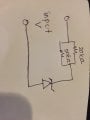
For a while I was pretty sure that the TVS diode (DZ1) might have failed as that would put high voltage on the drain pin, but it shows forward voltage of 0.6 and doesn't show anything in the reverse direction. I'm not sure how I can check it for proper 'TVS' operation.
The full schematic can be found https://elektrotanya.com/bose_l1_compact_system_service_manual.pdf/download.html
Thanks in advance.
P.S: I have got another unit which came in for repairs and the capacitor and the resistor of the LPF was burned up and bulged on that one. The SMPS IC was cracked open on that one as well. I also checked those components on the unit I'm currently working on and they test out ok.
I've recently got a Bose L1 compact sound system in for repair. The unit failed to power up one fine day.
After opening the unit up the first thing I noticed was the TOP258 IC was cracked open. Before replacing the IC I had a look for any other components which might have failed. I checked for the obvious culprits and I couldn't find anything which has failed. I checked the diodes and resistors around the IC, checked the main filter caps and the electrolytics near the IC. Checked the secondary side for any shorts or failed caps and nothing . I checked the capacitors with the ESR meter, I removed some capacitors and checked them with my multimeter for the capacitance value as well.
So after much contemplation, I decided to change the IC only but the thing was I couldn't get hold of any TOP258 ICs. So I placed order for those. However I had TOP256 IC in my parts bin. It can handle low power than the 258 and to see if anything else failed I replaced it with it (until I got the 258). Powered it up and it was working. Obviously I didn't run it at full volume or had it on for long.
After week of intermittently testing again the unit stopped powering up. Opened it up the SMPS IC was cracked open. Same story as before nothing else seems to have failed. I now have got the TOP258 IC but am afraid the same thing would happen unless I could find the culprit.
I have checked the speakers thinking they might have partly shorted and might have been drawing too much current. They also test out ok. The amplifier IC is TDA8920B. On the datasheet the amp chip and the TOP258 seems to have all the protection in the world and seems to be bullet proof.
I was hoping someone could shed some light on how to proceed and what else to look for.
I have attached a pdf of the power supply schematic.
For a while I was pretty sure that the TVS diode (DZ1) might have failed as that would put high voltage on the drain pin, but it shows forward voltage of 0.6 and doesn't show anything in the reverse direction. I'm not sure how I can check it for proper 'TVS' operation.
The full schematic can be found https://elektrotanya.com/bose_l1_compact_system_service_manual.pdf/download.html
Thanks in advance.
P.S: I have got another unit which came in for repairs and the capacitor and the resistor of the LPF was burned up and bulged on that one. The SMPS IC was cracked open on that one as well. I also checked those components on the unit I'm currently working on and they test out ok.
Attachments
-
81.6 KB Views: 8