Replacing Capacitors on a guitar amplifier power board

Thread Starter

Aues

Joined Jun 2, 2021
14
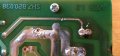
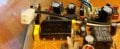
I have a Kustom 200 watt guitar amplifier head, it's several years old. When I plugged it in to test a new set of speakers I had built, it seemed to power on, but I couldn't get any sound out of it. (lights came on, all the channels seemed to be selecting properly, etc..) I opened it up, and found that one of the capacitors on the power board had completely fallen off the board. The positive pole wire was broken off to about 1/32 of an inch long, and the negative wire had apparently come unsoldered from the board. These are Aluminum Electrolytic Capacitors, 6800uf, 63V. I also noticed that on the other side of the board, from the positive connection of this cap, the solder line appears to be interrupted/broken in a spot, but it looks like it was that way from the factory. Sooo...the questions I have are; 1) What could make the capacitor fall off the board like this, and 2) When I replace the capacitors, should I also reconnect the solder line that appears to be broken by soldering it together. I've included pictures of the capacitor with the broken pole wire, the board showing the broken solder line, and also the piece on the board that this line goes to. The solder connection also goes to other components in the other direction, but this is the only thing it goes to where the line is broken. I'm not sure what this item on the board is either, so any help with that would be appreciated also! :)

Thanks for any help anyone can give me with this!
 

Attachments

MrChips

Joined Oct 2, 2009
30,810
Let's do one thing at a time.

Get the proper replacement capacitor.
When you install the capacitor make sure that it is oriented correctly with respect to polarity.
Bend the leads on the solder side of the board so that the leads will physically secure the capacitor.
Cut off the excess lead, leaving about 1/4 inch (5mm) on the bent end.
Solder using correct soldering technique.

I don't see a break in the PCB track, just a break in the solder track laying on top of the copper track.
If it makes you happy, bridge the solder gap with some fresh solder. It will make no difference.
 

Thread Starter

Aues

Joined Jun 2, 2021
14
Let's do one thing at a time.

Get the proper replacement capacitor.
When you install the capacitor make sure that it is oriented correctly with respect to polarity.
Bend the leads on the solder side of the board so that the leads will physically secure the capacitor.
Cut off the excess lead, leaving about 1/4 inch (5mm) on the bent end.
Solder using correct soldering technique.

I don't see a break in the PCB track, just a break in the solder track laying on top of the copper track.
If it makes you happy, bridge the solder gap with some fresh solder. It will make no difference.
Thanks for your swift reply!

Yes, I already have the proper replacements, they were relatively easy to find at Digi-Key. The board is also clearly marked for polarity, and I will definitely pay attention to that when installing them.

I was of the same opinion about the gap in the solder line, but I just wanted to make sure, as I am fairly new to repairing things like this. I have quite a bit of experience with wiring other things though, so I'm not finding it too difficult.

Do you have any idea why this capacitor would fall off the board like it did? I'm a little concerned that some other component could be damaged. I have really looked the board over carefully, and don't see anything obvious, but I know sometimes this kind of thing doesn't really show as damage.
 

Thread Starter

Aues

Joined Jun 2, 2021
14
Thanks to whoever moved this, for moving it to the correct forum, I noticed after I had posted it that it should have gone here in the first place. My apologies for being of trouble with my first post! :)
 

Alec_t

Joined Sep 17, 2013
14,314
What could make the capacitor fall off the board like this
I'd guess the amp has been dropped on to a hard surface, or knocked heavily. The heavier components (large caps, transformers etc) are most likely to suffer damaged connections. It's worth inspecting the circuit board under high magnification for any hair-line cracks/track damage.
 

Thread Starter

Aues

Joined Jun 2, 2021
14
Ok. Thanks Alec_t and Mr. Chips! I will check it one more time, and will post again whether or not it works! :)
 
Top