3 wire US Solid Ball valve

Thread Starter

midiean

Joined Jun 17, 2020
6
I'm working on a project to power a US Solid, 3 wire, motorized ballvalve. I have very little exprience, so please bear with me.
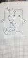
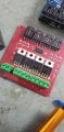
This particular ballvalve has a common load wire, and is switched by its nuetral circuit being connected. I was attempting to use mosfets with a 4 mosfet board to control the valves by wiring them to a 3 hole terminal, putting LEDs to isolate each load source. Any assistance in helping this newb figure out this problem, would be greatly appreciated.
 

Attachments

drc_567

Joined Dec 29, 2008
1,156
From the manufacturer's video:
valve wiring,
... It looks as if there could be a single Mosfet between + and red, and another Mosfet between + and black, with yellow always connected to negative.
The remaining question is how are the Mosfets to be activated? You only want one single Mosfet to be on at a time. Do you have a switch, a microcontroller, or some other way to activate the Mosfet gate voltages?
... Can you provide more explanation regarding load, leds ... maybe draw a sketch?

Note: This particular arrangement appears to be something called 'high side' switching, and calls for a particular type of Mosfet ... A P-channel Mosfet, where the load is 'below' the transistor. ...
 
Last edited:

Thread Starter

midiean

Joined Jun 17, 2020
6
From the manufacturer's video:
valve wiring,
... It looks as if there could be a single Mosfet between + and red, and another Mosfet between + and black, with yellow always connected to negative.
The remaining question is how are the Mosfets to be activated? You only want one single Mosfet to be on at a time. Do you have a switch, a microcontroller, or some other way to activate the Mosfet gate voltages?
... Can you provide more explanation regarding load, leds ... maybe draw a sketch?

Note: This particular arrangement appears to be something called 'high side' switching, and calls for a particular type of Mosfet ... A P-channel Mosfet, where the load is 'below' the transistor. ...

I'm activating the circuit using an Arduino controller atm. the LED was meant to be an indicator light as to which direction was operating, as well as prevent the flow of current back up the other mosfet lead. I really don't know if i'm explaining this correctly, or drawing this correctly either lol. in fact, i'm pretty sure my drawing just confused me. here's a picture of what I've got going on right now. the LED's are an attempt at controlling the direction of the flow so it doesn't destroy the mosfets. The LED's light up when the circuit is activated, so there is a good ground connection through the circuit. however, it isn't powering the circuit.
 

Attachments

shortbus

Joined Sep 30, 2009
10,045
Go back and look at the Youtube video, from around 35 seconds, at how the wires are done. Your drawing shows the yellow wire going to what I assume in your drawing is the mosfets gates. That won't work and you show the diode blocking any flow of electricity.

The yellow wire is the negative/ground/common from the valve. The red wire will be positive to turn the valve one way, and blue will be positive to make it go the other. Only one, red or blue can be on at a time. But the yellow always needs to be connected to negative.
 

Thread Starter

midiean

Joined Jun 17, 2020
6
Go back and look at the Youtube video, from around 35 seconds, at how the wires are done. Your drawing shows the yellow wire going to what I assume in your drawing is the mosfets gates. That won't work and you show the diode blocking any flow of electricity.

The yellow wire is the negative/ground/common from the valve. The red wire will be positive to turn the valve one way, and blue will be positive to make it go the other. Only one, red or blue can be on at a time. But the yellow always needs to be connected to negative.
Correct. my drawing may not make a lot of sense, it didn't to me. I'm still very new to this and what i'm trying to do is above my level of understanding. I understand I need the power fed through the yellow wire and the blue and red are the returns. the LED's were meant to keep the direction flowing one way when the mosfet was powered on that particular pair of yr/yb.
 

djsfantasi

Joined Apr 11, 2010
9,163
The LEDs only need ~20mA. If they are in series with the solenoid coils, they’re going to get a lot more current. *Poof* The LEDs will fail and nothing will work.
 

Thread Starter

midiean

Joined Jun 17, 2020
6
The LEDs only need ~20mA. If they are in series with the solenoid coils, they’re going to get a lot more current. *Poof* The LEDs will fail and nothing will work.
these are motorized ball valves, not solenoids. they only draw power during the transition, not to hold open
 

Reloadron

Joined Jan 15, 2015
7,523
I understand I need the power fed through the yellow wire and the blue and red are the returns.
No, the yellow wire is the valve body negative, common or ground. That will remain always connected. You switch between positive to the blue and red to open or close the valve. Using an Arduino try a Google of P channel mosfet switch. Two P channel mosfets and two digital out pins is all you need. You also only need to pulse the valve for about 5 sec. So you digitalWrite a pin LOW for 5 sec to open or close.

Ron
 

Thread Starter

midiean

Joined Jun 17, 2020
6
so, the red and blue wire, according to the schematic, are the + legs of the connection, and the yellow is the - selection. a SPDT switch is what i'm trying to figure out. the P Channel mosfets are what I need to be using to switch on the high end, but they require a 10v signal to activate. From what I can gather, I need to figure out an H bridge to simulate that action with mosfets, but I have not the knowledge to be able to figure that one out with out melting a number of components.
 

drc_567

Joined Dec 29, 2008
1,156
... I think the gate of the P channel turns the trasnsistor on when you connect it to ground, or negative.
... Not sure what you need for positive terminal of the Mosfet, you need to look at the datasheet specification.
If your plan includes an Arduino, it is necessary to connect the Arduino ground pin and the Mosfet ground terminals. Then, when you write a low signal to the Arduino Analogout pin, the Mosfet
gate goes low and turns on.
... If you had N channel Mosfets, then +10 to the gate would be correct, but for the P channel, the gate should be grounded.
 

MisterBill2

Joined Jan 23, 2018
18,566
Quite an interesting discussion in that most of the focus has been on driver circuits without much consideration of the valve motor requirements.
Note that the power is listed as AC OR DC, with one common return line and separate supplies for open and close. So there are internal limit switches to stop the motor at either end of the motion.
What supply voltage is easily available in the associated control system?
AND, since internal switches are part of the valve, it could be driven with a single SPDT relay. That is another option.
 

shortbus

Joined Sep 30, 2009
10,045
Note that the power is listed as AC OR DC
And by the blurb on the US Solid website you know which type he is working with? It says AC OR DC not both in the same valve. They have different pages and part numbers for the different power types. But then again it take reading skills to see that. Or you have a better crystal ball than the rest of us.
 

MisterBill2

Joined Jan 23, 2018
18,566
And by the blurb on the US Solid website you know which type he is working with? It says AC OR DC not both in the same valve. They have different pages and part numbers for the different power types. But then again it take reading skills to see that. Or you have a better crystal ball than the rest of us.
As a matter of fact, by the photo of the tag in post #1 where it states "9-24 V AC/DC" I tend to think that they mean both. That is rather plain english as I see it.
 

Reloadron

Joined Jan 15, 2015
7,523
For anyone curious enough:

U.S. Solid
1200 E 55th St
Cleveland, OH 44103
1-800-243-5428

Surprise me but that address is a few miles from my front door. Anyway, they do have a 1-800 phone listing so anyone curious enough can call them. I have no clue if their products are made here or abroad but Cleveland is home to quite a bit of manufacturing.

Ron
 
Top