
Hello all!
I'm working on a project that requires data to be sent and received over optic fiber cables, specifically TOSLink cables. Ideally, for this project, I want to use these RS232 "bricklets" made by Tinkerforge, which also have a TTL interface I can connect TOSlink transmitters/receivers to.
https://www.tinkerforge.com/en/doc/Hardware/Bricklets/RS232_V2.html
I have chosen the following transmitter and receiver from Sys-Concept:
http://www.sys-concept.com/toslink_receiver_files/Toslink-TX-Data-16Mbps-Sys.Concept.pdf
http://www.sys-concept.com/toslink_receiver_files/Toslink-RX-Data-16Mbps-Sys.Concept.pdf
For prototyping/testing, I have been able to connect two RS232 bricklets (V2) to a Tinkerforge "master brick", connect a receiver to the TTL interface on one RS232 bricklet and a transmitter (with a 150 nF bypass capacitor) to the other TTL interface on the other RS232 bricklet, and send messages without a problem.
Now, I am hoping to connect both a receiver and a transmitter to a single TTL interface on an RS232 bricklet. I connected a single transmitter to the other RS232 bricklet and sent a message to the receiver/transmitter combo just fine. However, when I connected a single receiver to the other RS232 bricklet and sent a message from the receiver/transmitter combo, the transmitter appears to just send a stream of never-ending gibberish noise over the TOSLink cable.
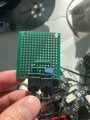
In short, the circuit I have built involves connecting the 3.3V pin to both Vcc pins on the receiver and transmitter, the ground pin to both GND pins on the receiver and transmitter, and the RX1/TX pins to their respective Vin pins on the receiver/transmitter (see attached photos). I put a 150nF bypass capacitor between the Vcc and GND pins on the transmitter.This entire circuit is soldered on a perfboard. I was thinking I might need a bypass capacitor for the receiver, but the receiver didn't need one when a single receiver was attached to the TTL interface.
Any suggestions, advice, or insight on what might be happening would be great! I pretty new to electronics like this, and I wasn't quite sure where I could get help because there isn't too much information online, so I thought I would try here. I am happy to provide any more information that is needed. Thank you!
Sincerely,
Ryan
I'm working on a project that requires data to be sent and received over optic fiber cables, specifically TOSLink cables. Ideally, for this project, I want to use these RS232 "bricklets" made by Tinkerforge, which also have a TTL interface I can connect TOSlink transmitters/receivers to.
https://www.tinkerforge.com/en/doc/Hardware/Bricklets/RS232_V2.html
I have chosen the following transmitter and receiver from Sys-Concept:
http://www.sys-concept.com/toslink_receiver_files/Toslink-TX-Data-16Mbps-Sys.Concept.pdf
http://www.sys-concept.com/toslink_receiver_files/Toslink-RX-Data-16Mbps-Sys.Concept.pdf
For prototyping/testing, I have been able to connect two RS232 bricklets (V2) to a Tinkerforge "master brick", connect a receiver to the TTL interface on one RS232 bricklet and a transmitter (with a 150 nF bypass capacitor) to the other TTL interface on the other RS232 bricklet, and send messages without a problem.
Now, I am hoping to connect both a receiver and a transmitter to a single TTL interface on an RS232 bricklet. I connected a single transmitter to the other RS232 bricklet and sent a message to the receiver/transmitter combo just fine. However, when I connected a single receiver to the other RS232 bricklet and sent a message from the receiver/transmitter combo, the transmitter appears to just send a stream of never-ending gibberish noise over the TOSLink cable.
In short, the circuit I have built involves connecting the 3.3V pin to both Vcc pins on the receiver and transmitter, the ground pin to both GND pins on the receiver and transmitter, and the RX1/TX pins to their respective Vin pins on the receiver/transmitter (see attached photos). I put a 150nF bypass capacitor between the Vcc and GND pins on the transmitter.This entire circuit is soldered on a perfboard. I was thinking I might need a bypass capacitor for the receiver, but the receiver didn't need one when a single receiver was attached to the TTL interface.
Any suggestions, advice, or insight on what might be happening would be great! I pretty new to electronics like this, and I wasn't quite sure where I could get help because there isn't too much information online, so I thought I would try here. I am happy to provide any more information that is needed. Thank you!
Sincerely,
Ryan
Attachments
-
 1.8 MB Views: 2
 -
 1.9 MB Views: 2


