measure,Identify ferrite bead smd and inductor smd

Thread Starter

PnppNpnn

Joined Dec 29, 2018
6
Hi guys,

decided to ask. maybe someone came across this, but I did not find how to identify a damaged element.
In general, I need an element identification.
since many manufacturers of SMD components it is very difficult to identify them without special expensive equipment.
The circuit schematic is not available.
From the available one there is an oscilloscope of 1 GHz. (From a calibration signal) And there is a signal of a reference oscillator of 10 MHz.
I was able to find one whole, and made measurements of dimensions and resistance.
dimensions:
L=2.04 W=1.31 H=0.87mm
electrical parameters:
R=70mΩ
What this element ?
L-? C-?
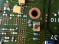
any ideas, Damaged item in the photo.
thanks.
 

Attachments

DarthVolta

Joined Jan 27, 2015
521
Hi the black part, is probably a It's quite possible it's just a fuse, or re-settable fuse, PTC.. could be inductor, Looks like it's under big IC. The big yellow cap is a 220uF , is it damaged ?

What is the PCB, what machine is it from? Are you saying this is from a 1GHz oscilloscope ?


I'd say start mapping the circuit to find if it's protection on a data line, or over current protection of some kind for a big chip. It doesn't look like it's part of any DC-DC converter, not in my expereience, so if it was an inductor, I wonder what kind of circuit it from.
 

jpanhalt

Joined Jan 18, 2008
11,087
The big capacitor next to it is a Kemet 2.2 uF (22 +5 zeros pF) 35V Tantalum capacitor. There are others on the same board.

As for the displaced device, I am not convinced it is ferrite or an inductor. Why do you think it is an inductor? Could be just a capacitor.
 

Thread Starter

PnppNpnn

Joined Dec 29, 2018
6
Hi the black part, is probably a It's quite possible it's just a fuse, or re-settable fuse, PTC.. could be inductor, Looks like it's under big IC. The big yellow cap is a 220uF , is it damaged ?
Hi, thanks guys for supporting me
I expected that one of the more experienced will give an answer, this is already a good result!
I met such gray-black components in computer technology, designated as "L" (on a printed circuit board)
It looks like a ferrite shell, the hue is not normalized,
many manufacturers hard to search.
The yellow tantalum capacitor is the lightest that can be detected, it is easy to replace,
it is not badly damaged, but I will replace it anyway.
The good ones were also emphasized by fuse, or re-settable fuse, PTC .. But now it will be more and more difficult to determine.
Could you give examples from a photo of a printed circuit board what it looks like (fuse, or re-settable fuse, PTC)? I met such, but they look completely different, I have not met them in this form. I refer to the manufacturer Littelfuse as a large assortment.


What is the PCB, what machine is it from? Are you saying this is from a 1GHz oscilloscope ?
The circuit board does come from an oscilloscope,
Damaged components located on the back of the circuit board under
large microcircuit, execution BGA.

For research, I have a working 1GHz oscilloscope.
I don’t have spectrum analyzers, a pulse generator, and most importantly I don’t have an LCR meter (for small inductances and capacity).


I'd say start mapping the circuit to find if it's protection on a data line, or over current protection of some kind for a big chip. It doesn't look like it's part of any DC-DC converter, not in my expereience, so if it was an inductor, I wonder what kind of circuit it from.
There is a difficulty in determining where the lines lead, they go under a large chip, and the chip itself is the property of the company that produced this equipment, there is simply no description,the line is pulled up, it can be seen from the photo with a tantalum capacitor, we can assume that this is a power line but this is not accurate. But you correctly noticed a little.
I have not seen similar clarifications on this topic, by definition of the components, there are many that these are noise-suppressing ferrite filters, I can assume that these elements can have several purposes ... Therefore, I am here, maybe someone has experience how to determine and by what method.


The big capacitor next to it is a Kemet 2.2 uF (22 +5 zeros pF) 35V Tantalum capacitor. There are others on the same board.

As for the displaced device, I am not convinced it is ferrite or an inductor. Why do you think it is an inductor? Could be just a capacitor.
I researched muRata catalogs with smd inductors and smd EMI Ferrite Bead,
I met gray-black components like this in similar sizes and colors.
I have not seen such capacitors in which the resistances are of the order of 0.070Ω, and have not seen such ones in color.
 

DarthVolta

Joined Jan 27, 2015
521
Ok it is an oscilloscope PCB. Some one on here will know a lot more about those. Please tell use the Oscilloscope model, and what section of the scope it might be?

Right right, I said 22*(10^-5), but it's 22*(10^5)*(10^-12) Farad, too tired to remember at that late hour.


As for a test to guess the range, without a tester or function generator, you could make a LC oscillator circuits, with good inductors, and then just try with your part, and see if it does anything. You might find range that way, if it's a uH or 100uH or instance.
 

Thread Starter

PnppNpnn

Joined Dec 29, 2018
6
As for a test to guess the range, without a tester or function generator, you could make a LC oscillator circuits, with good inductors, and then just try with your part, and see if it does anything. You might find range that way, if it's a uH or 100uH or instance.
Yes, I looked towards LC oscillator circuits, I don’t have sets of exact inductances.
I wanted to use the oscilloscope output as a generator, but there the waveform is not quite suitable and frequency.

If it is an EMI Ferrite Bead, then how to check?
They work at certain frequencies, suppressing all kinds of spurious interference signals.
What are your assumptions that this is an inductor?
It is not bad that someone from the environment gave an example with photos and circuits, from measuring equipment, where the circuits denominations of similar components are indicated,
in order to exclude unnecessary work and wasted time to nothing. So how will something to buy search, order, wait.
 

twohats

Joined Oct 28, 2015
447
Hi,
Why don't you compare it with the one in the upper left of the photo?
It's attached to a capacitor, identical to the in question.
Good luck,
twohats..
 

Thread Starter

PnppNpnn

Joined Dec 29, 2018
6
Hi,
Why don't you compare it with the one in the upper left of the photo?
It's attached to a capacitor, identical to the in question.
Good luck,
twohats..
hi,
I don 't understand your thoughts.Yes logically, it can be the same as defective.
What's next? There are no inscriptions on it. How to identify it and what category of components to assign?


Have everyone who reads this ever met such components?
No one is interested in how to determine their characteristics?
It 's gonna be good for everyone...
 

jpanhalt

Joined Jan 18, 2008
11,087
hi,
I don 't understand your thoughts.Yes logically, it can be the same as defective.
What's next? There are no inscriptions on it. How to identify it and what category of components to assign?


Have everyone who reads this ever met such components?
No one is interested in how to determine their characteristics?
It 's gonna be good for everyone...
Simple. What are your alternatives? Try it. If it works. Great. If it doesn't, ????
 
Top